
Hi! I'm Klemm! With the XWK-Bot, we'll explore the exciting world of robotics/mechatronics together!
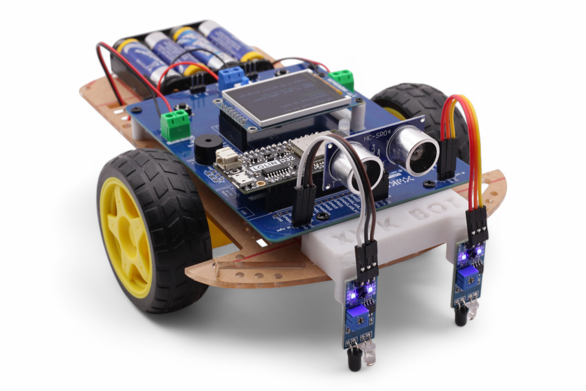
We'll build a driving robot that you can easily program yourself.
Mechatronics is an exciting mix of mechanics, electronics, and computer science
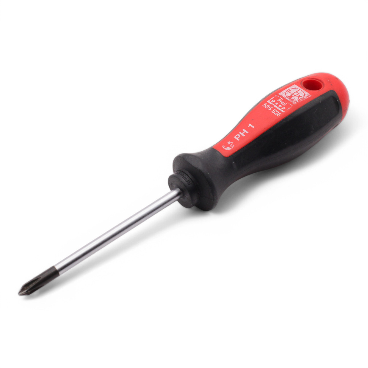
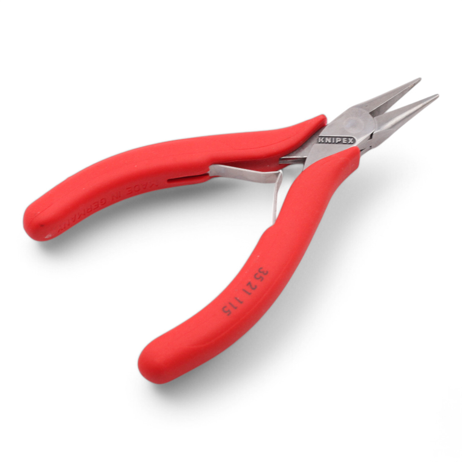
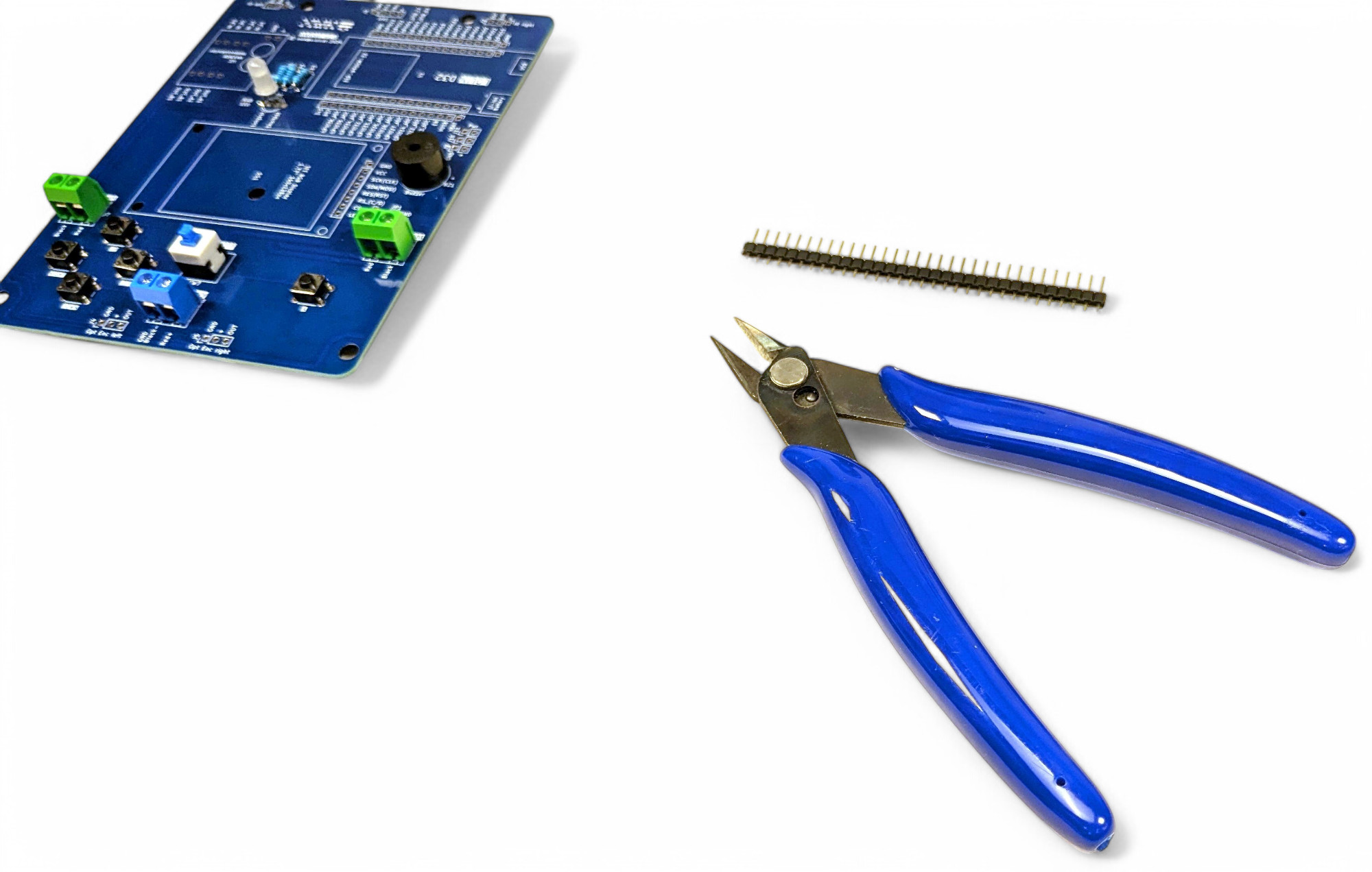
You'll need the following tools for assembly:

Not strictly necessary but useful:

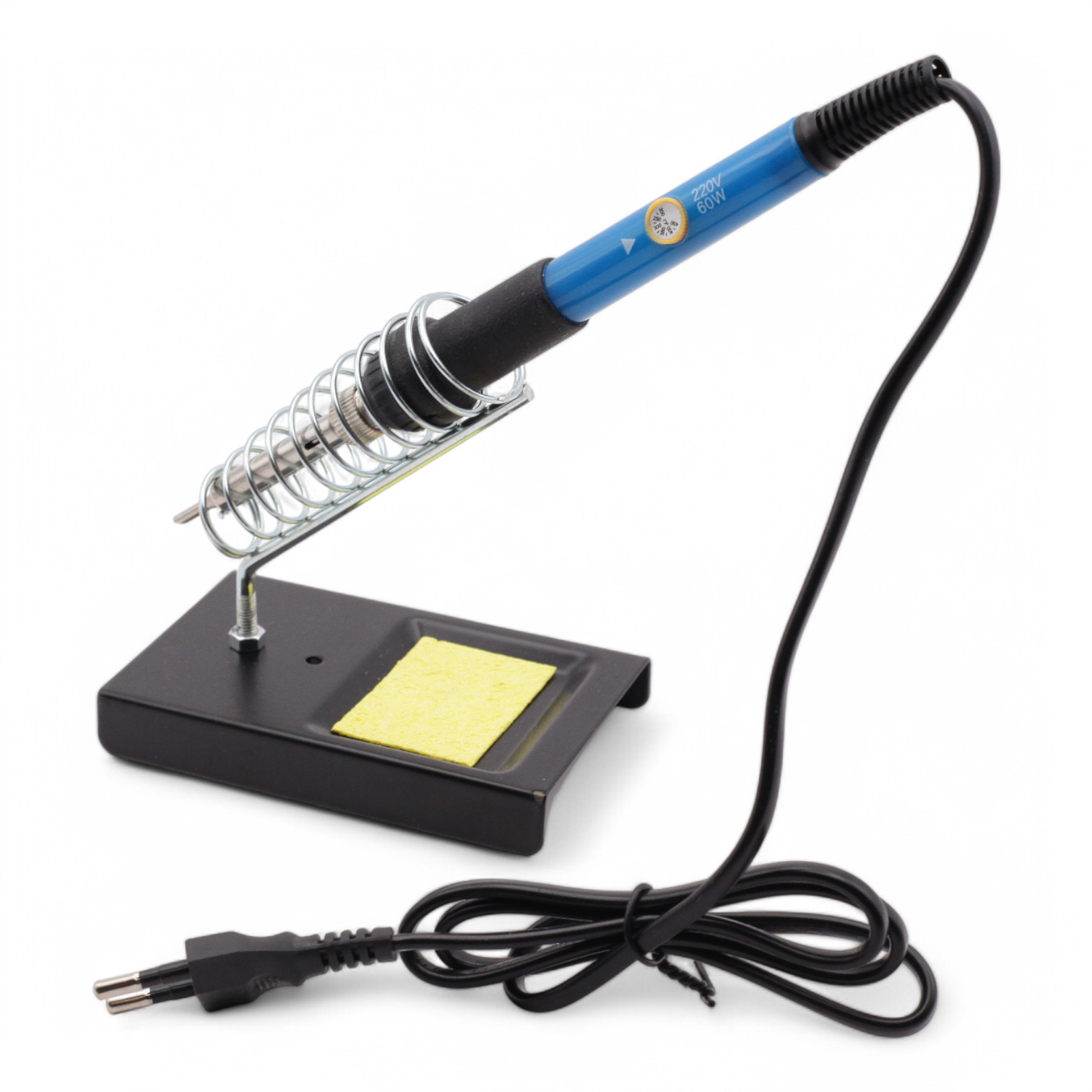
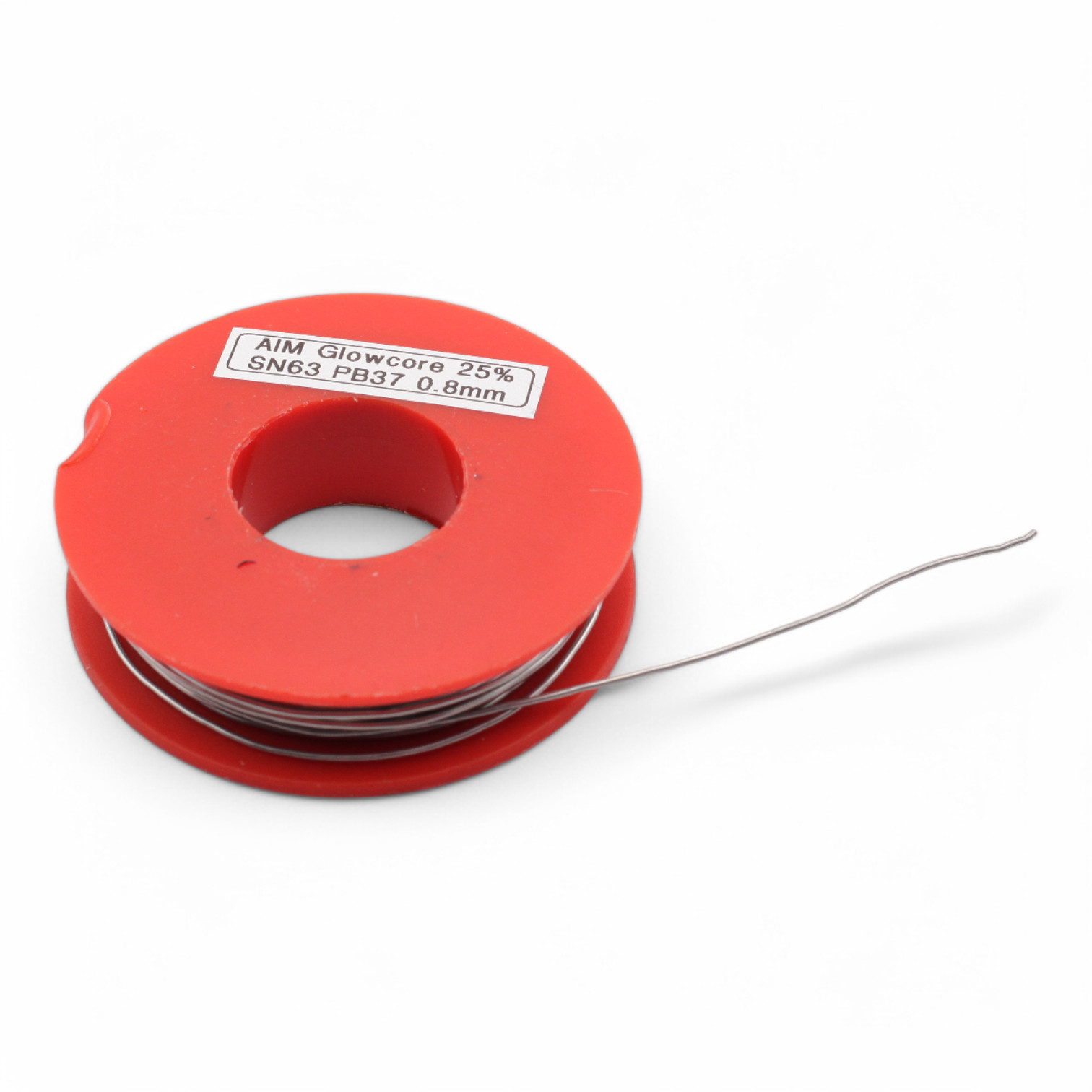
You need a soldering iron (preferably with a spiral stand and wet sponge) and solder. If you can set the temperature, choose 300°-350°. Wait 1-2 minutes until the soldering iron is hot. Don't be sad if it doesn't work right away, soldering takes practice. You can do it!
CAUTION - The soldering iron gets over 300°C hot - be careful not to burn yourself! - If you burn yourself, immediately hold the area under cold running water - Work in a well-ventilated room - Solder may contain toxic lead. Wash your hands well after soldering!
As a right-hander, hold the soldering iron in your right hand and the solder in your left hand. Rest your hands on the table so your palms touch the table. This will help you shake less. Don't leave the soldering iron on the joint unnecessarily long, as the component can be damaged by the heat! One second is completely sufficient.
Unwind about 5cm of solder and straighten it. Hold it ready with your left hand near the spot you want to solder.
Now touch the spot you want to solder with the tip of the soldering iron. Immediately bring the solder to the soldering iron tip and melt enough solder to wet the spot well. Not too much, not too little! If you can still see parts of the component, it was too little solder. If a ball forms, it was too much.
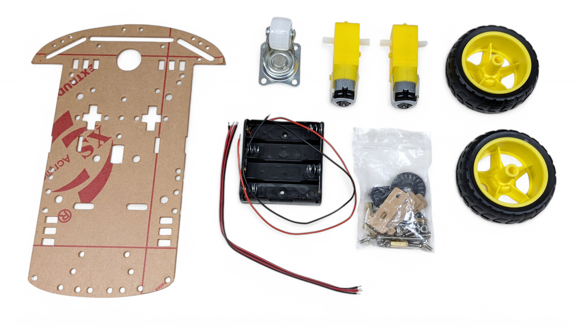
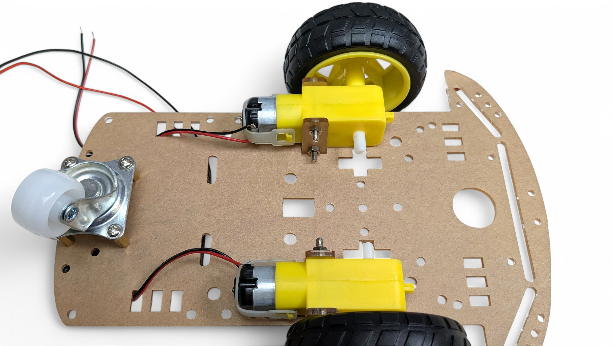
For assembling the chassis, you need the following parts:
First, we'll install the motors.
If the wires aren't soldered to the motors yet, we'll do that first. If you've never soldered before, read the instructions above!
Repeat the process with the black wire and then with the second motor.
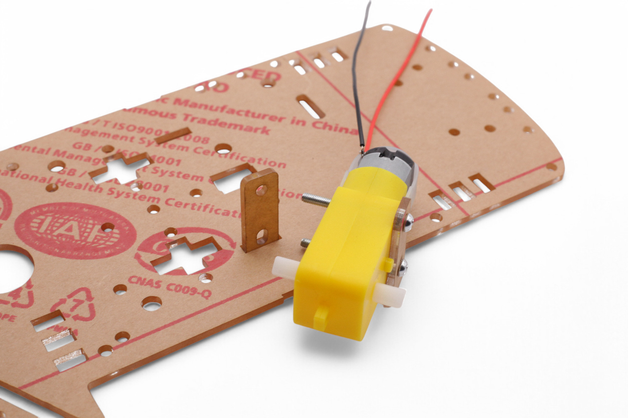
Let's start with one motor. This process requires some finger dexterity. Don't give up, you can do it!
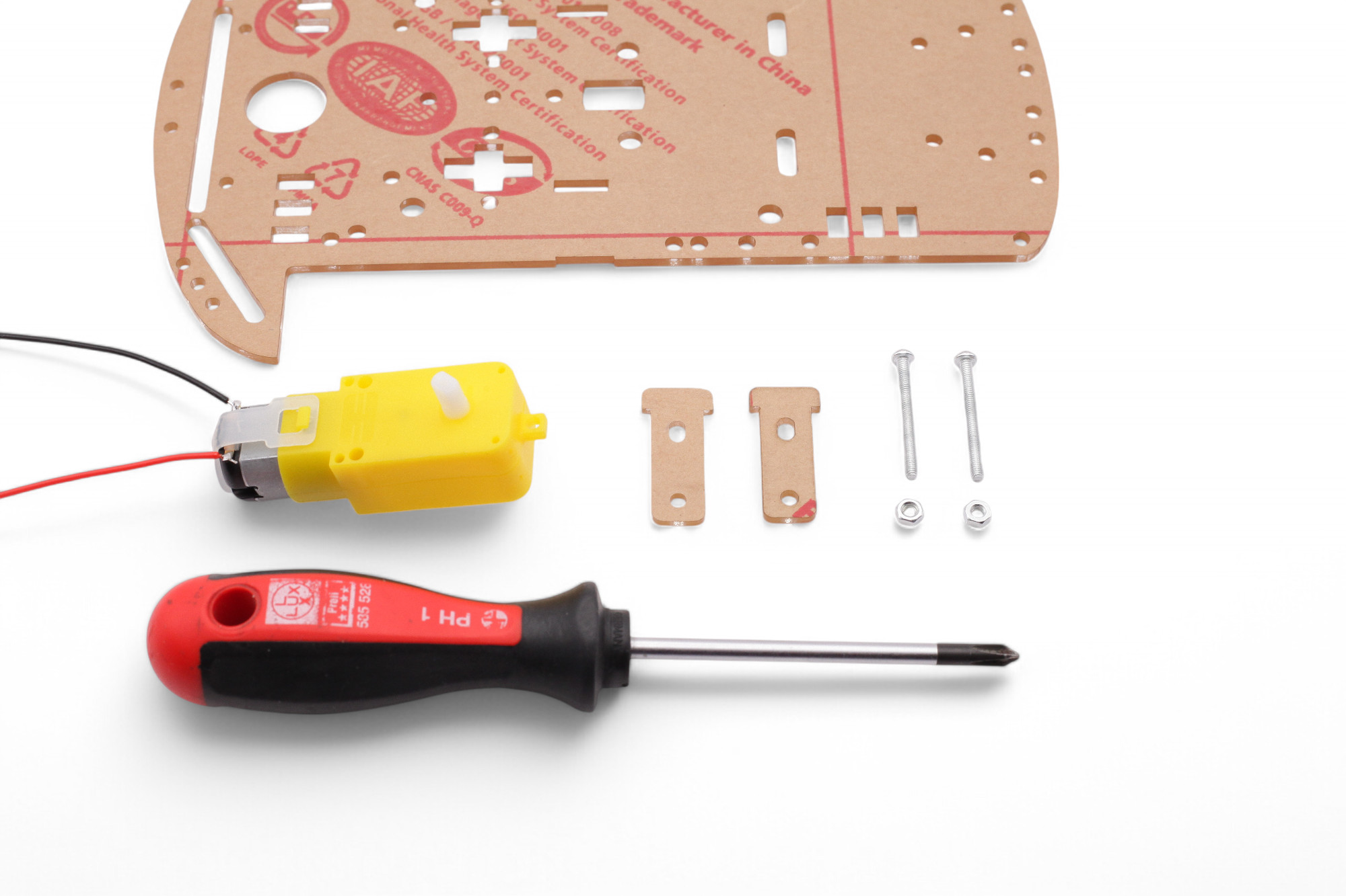
Hold the motor so that the connection wires face away from you. Then push two long M3 screws through the T-shaped plate and the motor:
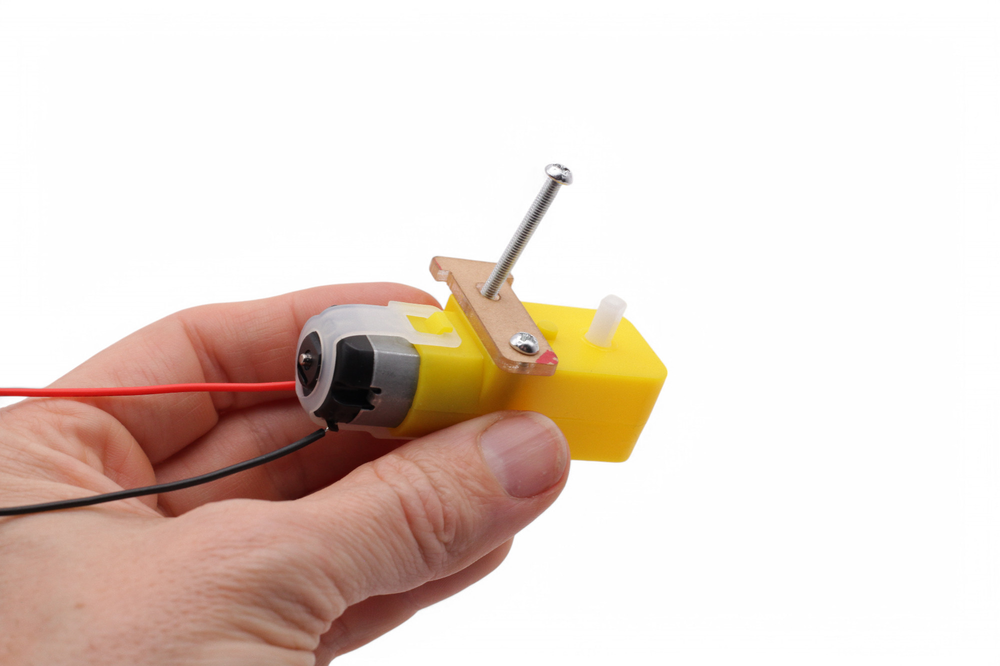
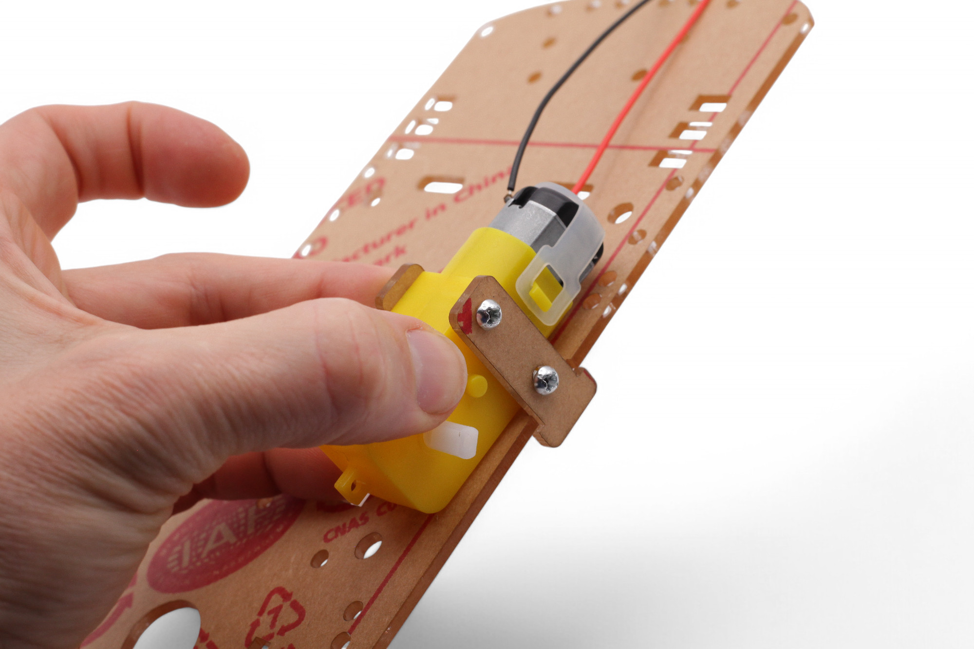
Push the other plate through the slot from above:
Turn the plate over and push the screws through the holes in the second plate. The first plate at the edge should fit into the small recess:
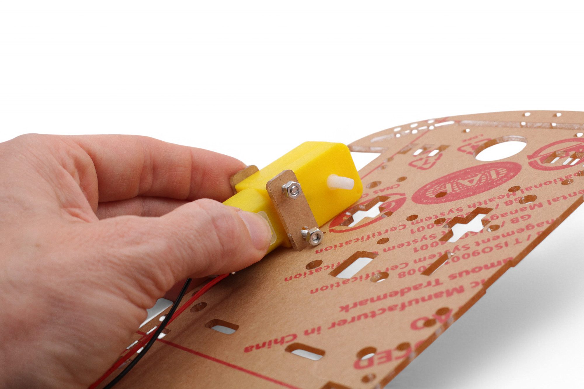
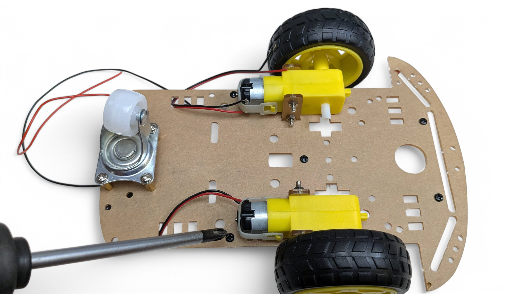
Now screw the nuts onto the screws and tighten them with a screwdriver:
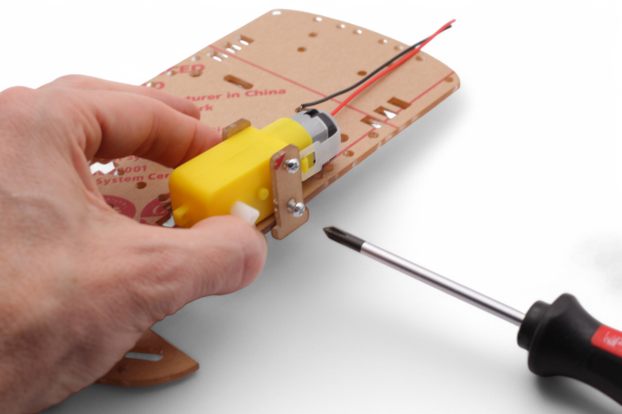
Repeat the whole process for the second motor in mirror image. Make sure the motor connection wires face inward.
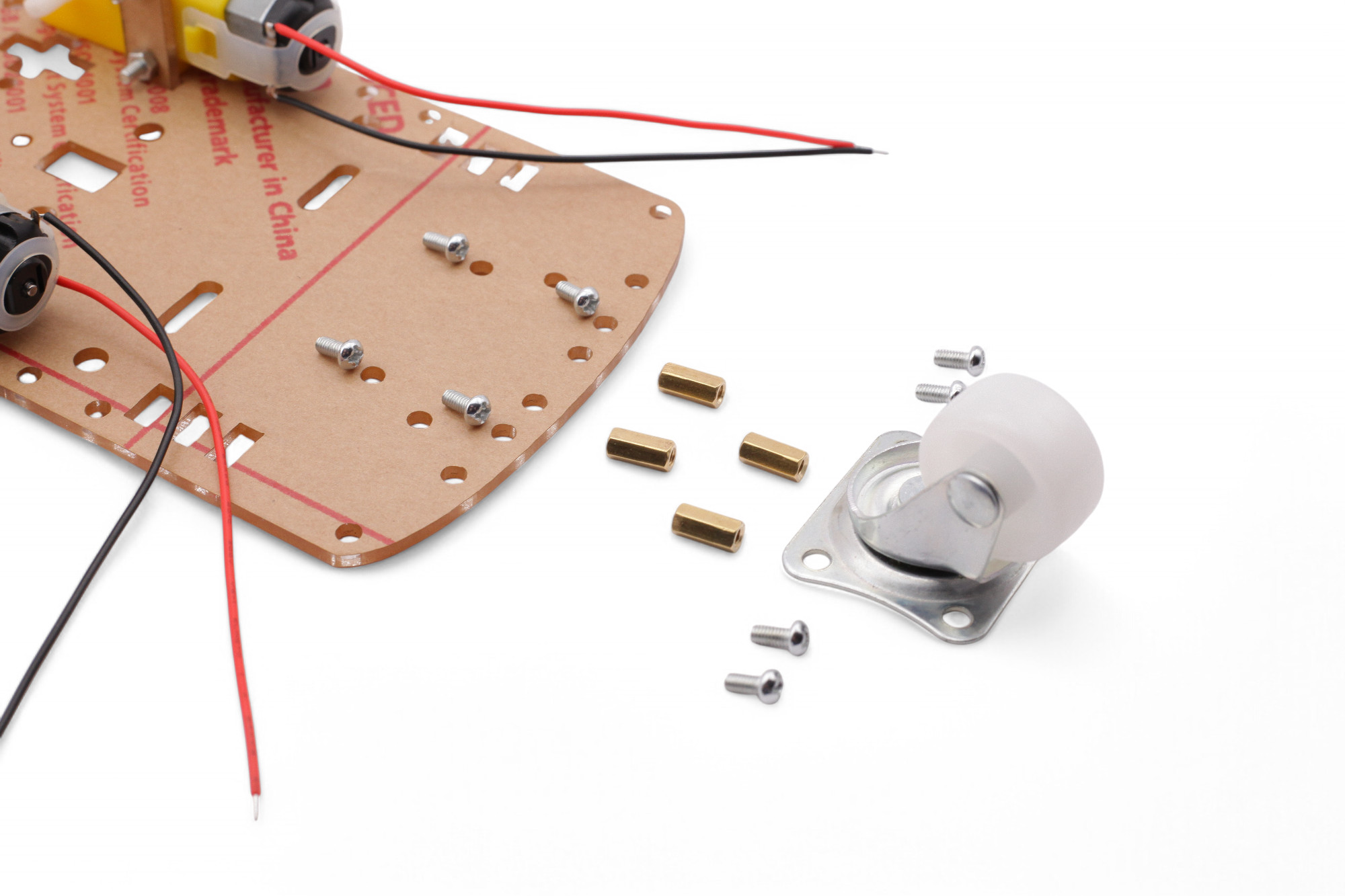
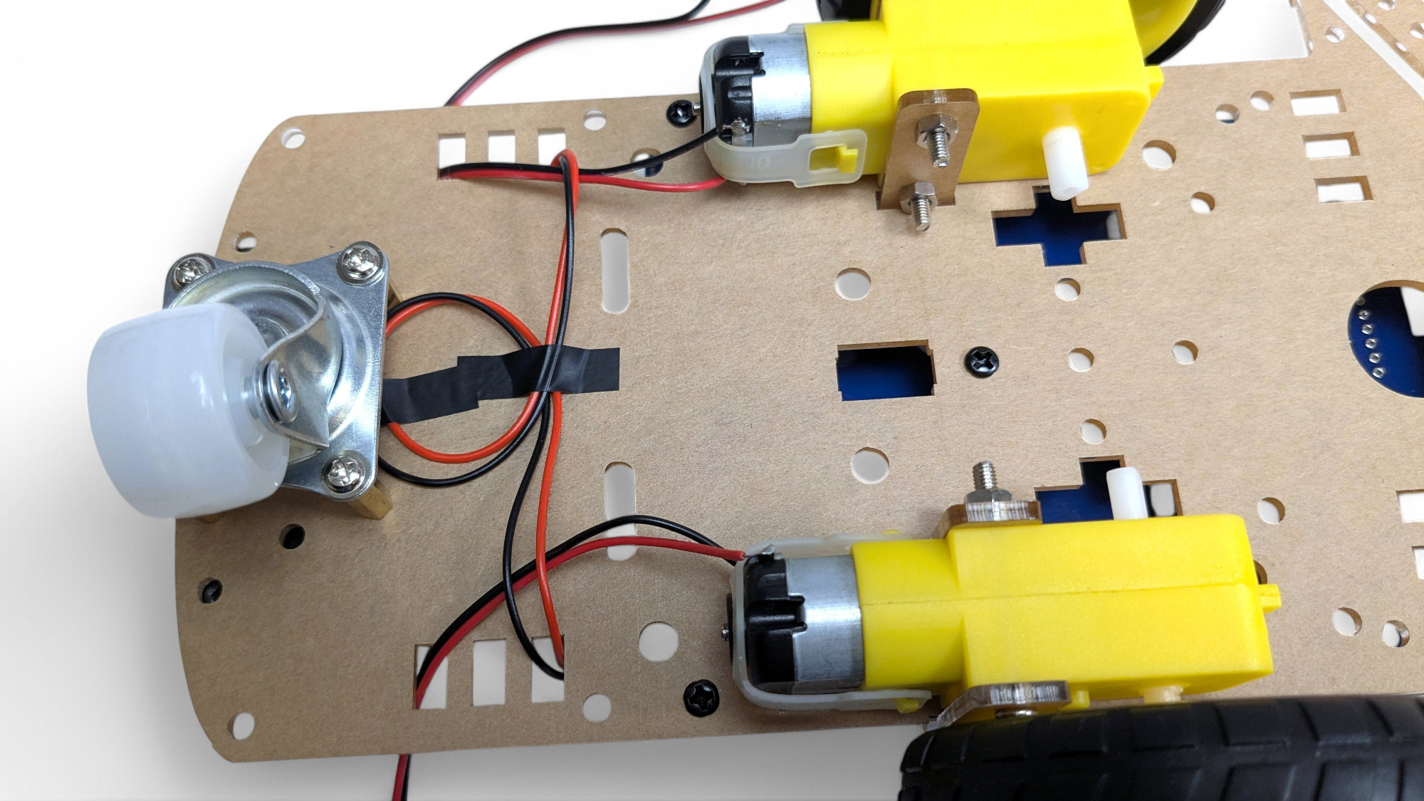
Now we'll mount the small wheel for the back. Look for these parts:
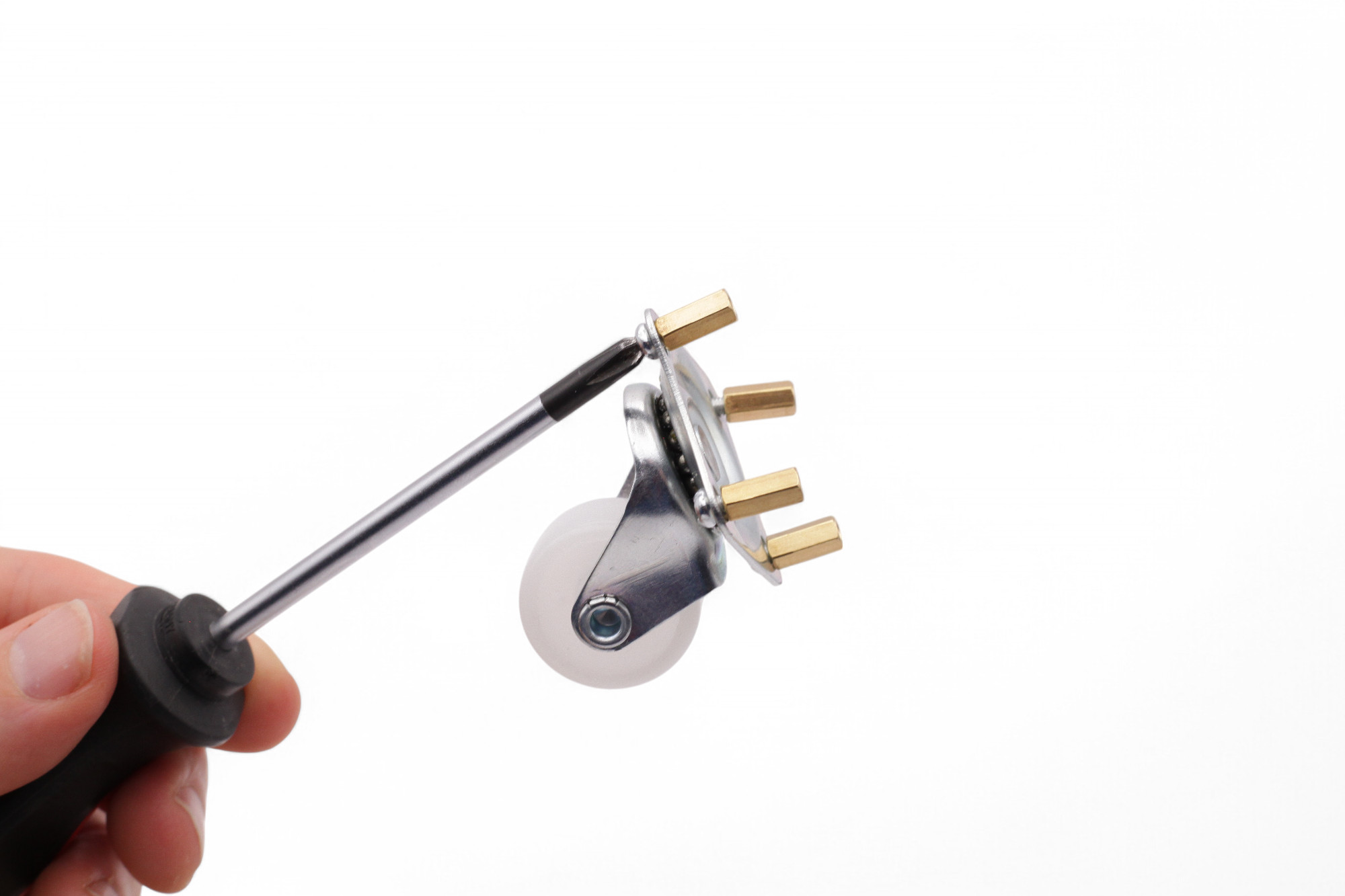
First, screw the brass extensions onto the wheel. Leave the screws loose!
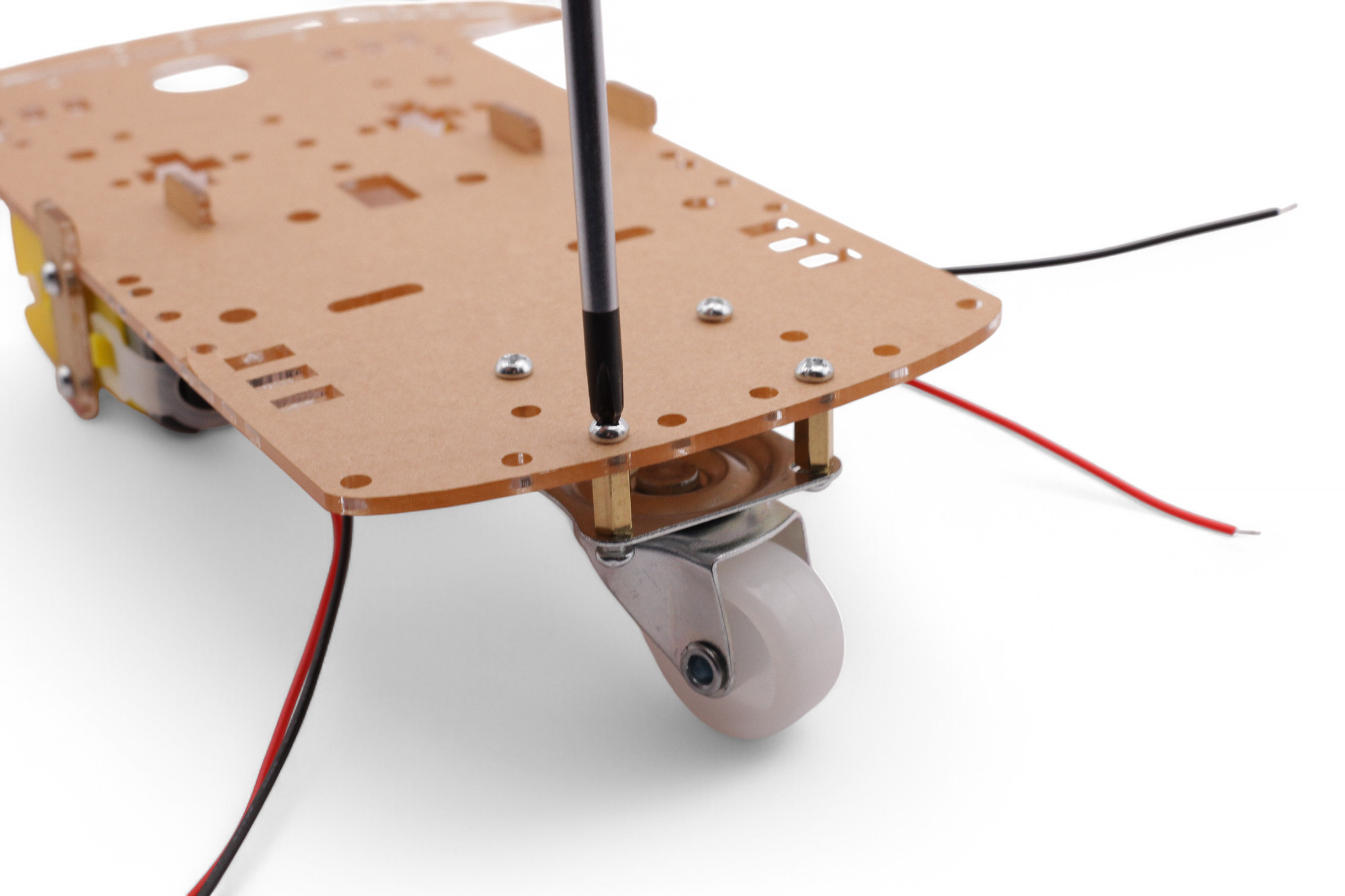
Then screw the wheel onto the plate. Now tighten all screws:
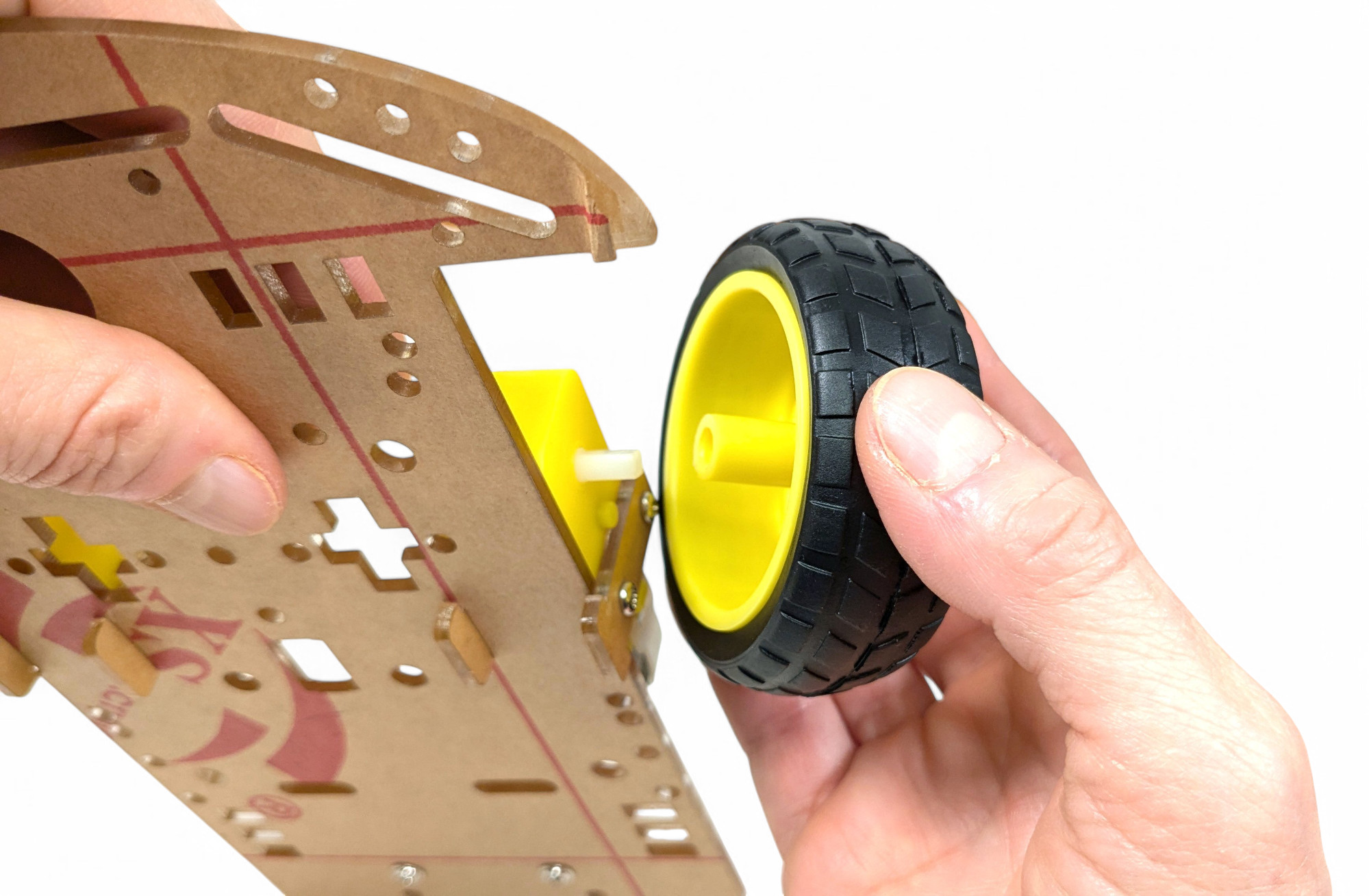
Now push the large wheels onto the motors:
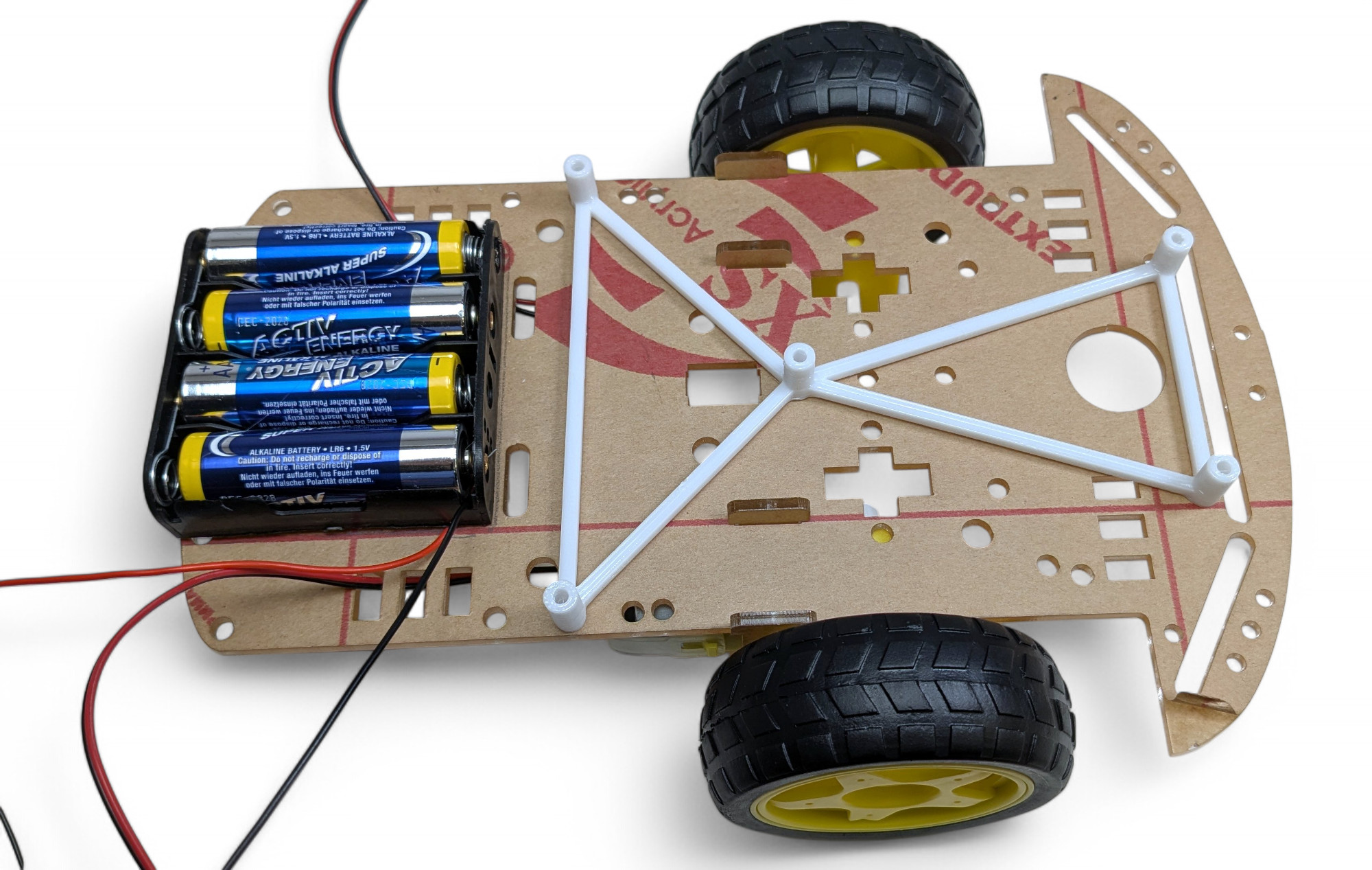
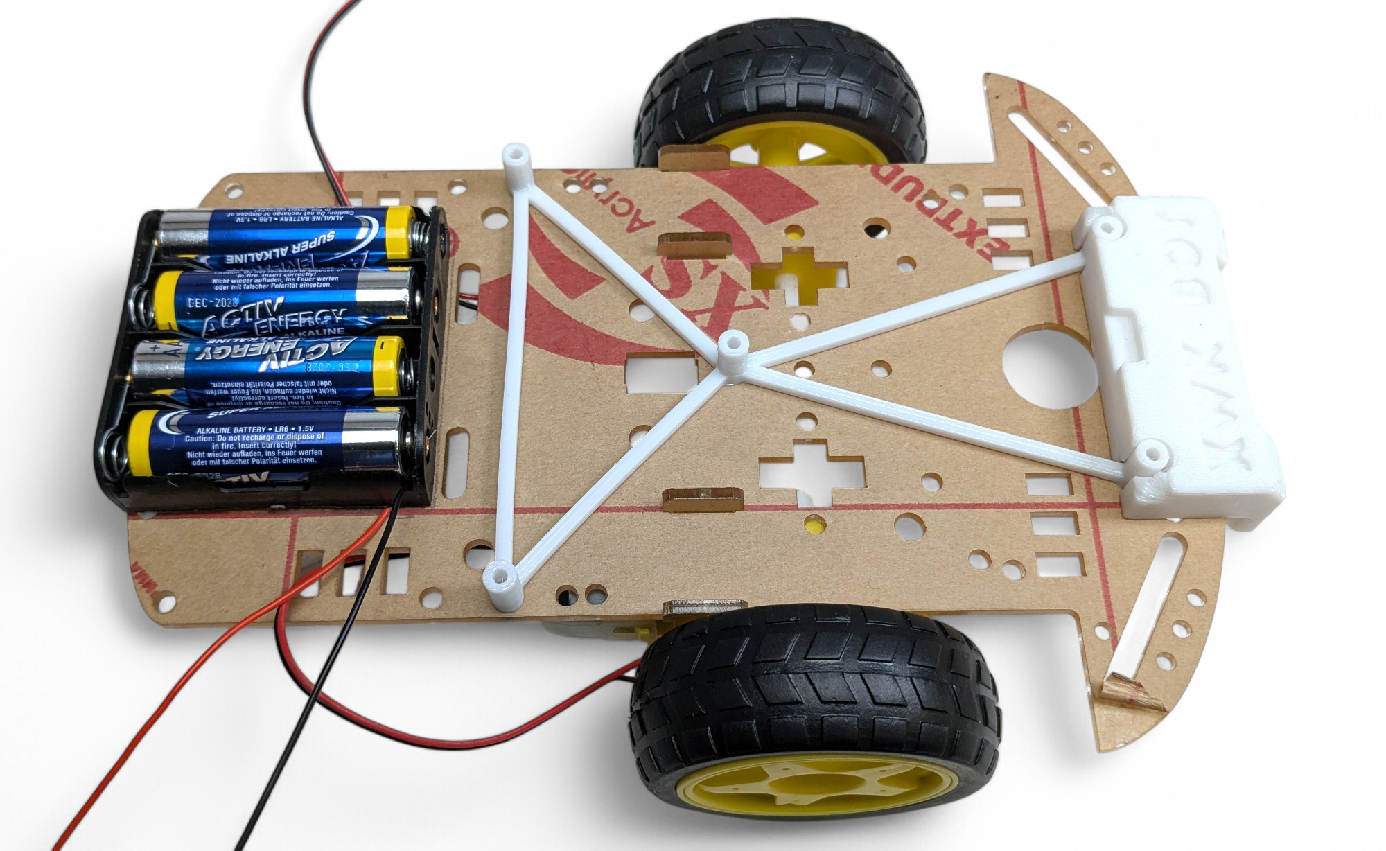
Cut two strips of thick double-sided tape and stick it to the underside of the battery holder:
Now peel off the protective film of the tape and stick the battery holder to the center of the base plate at the back - where the small rear wheel is. It should align with the base plate at the back:
Your chassis is ready! Congratulations!
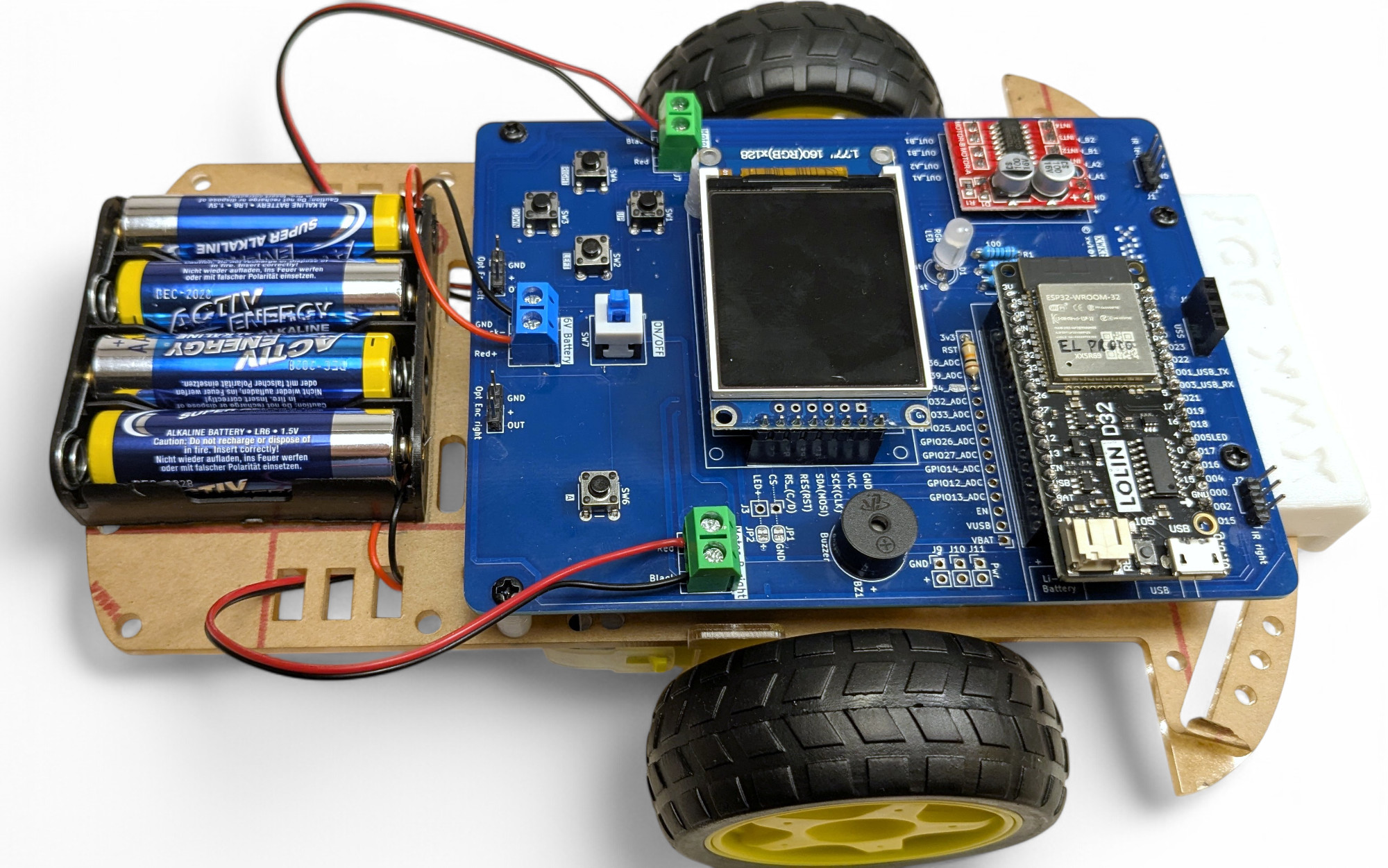
Next, we'll solder the components onto the circuit board. We're building a real little computer with a screen, buttons, and speaker!
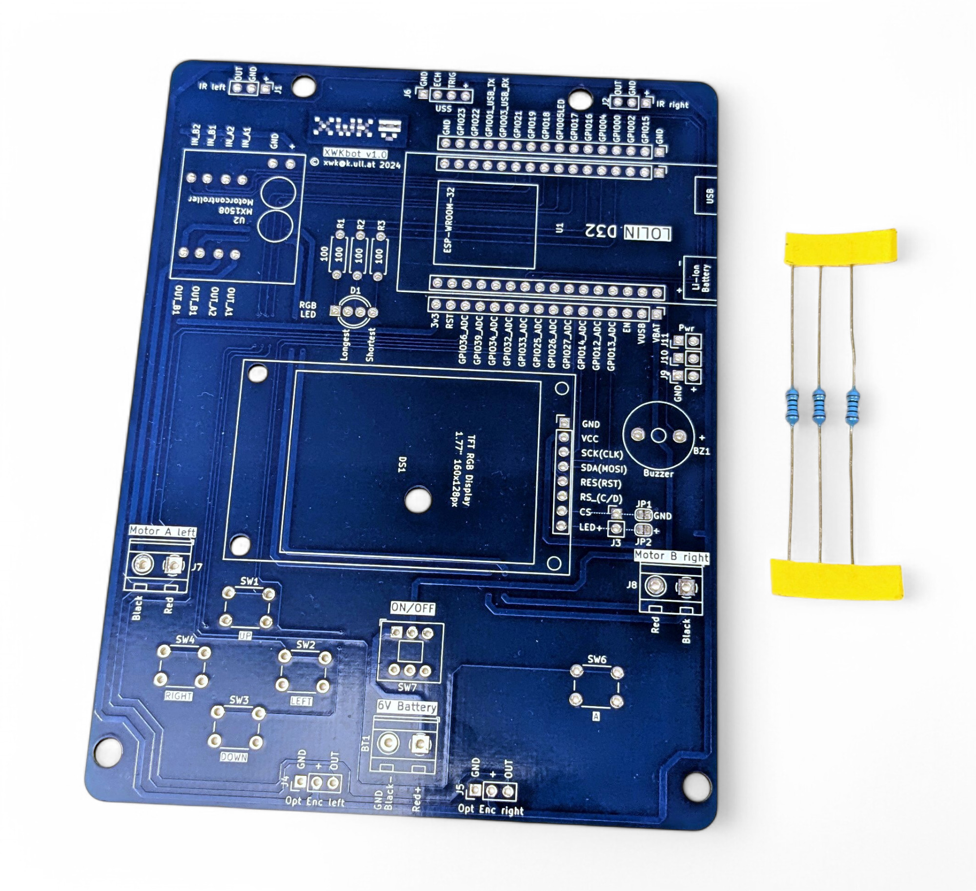
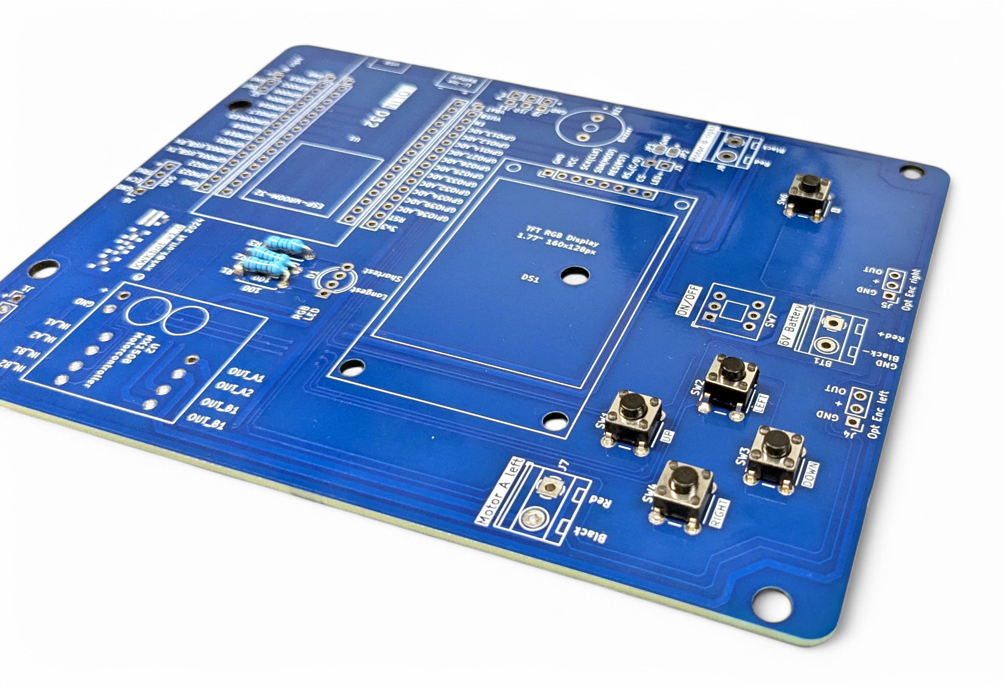
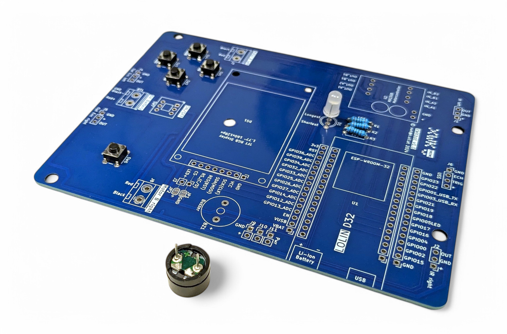
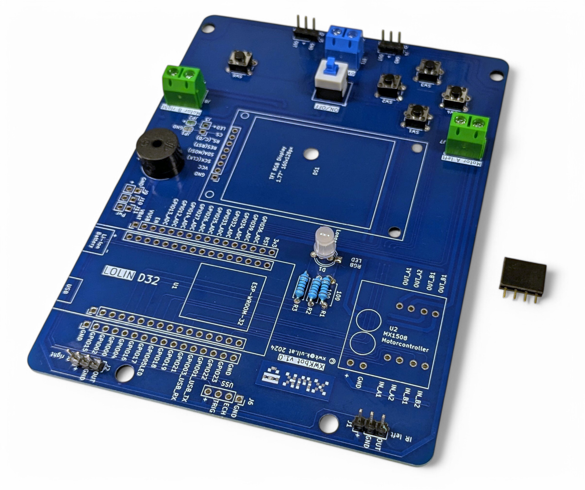
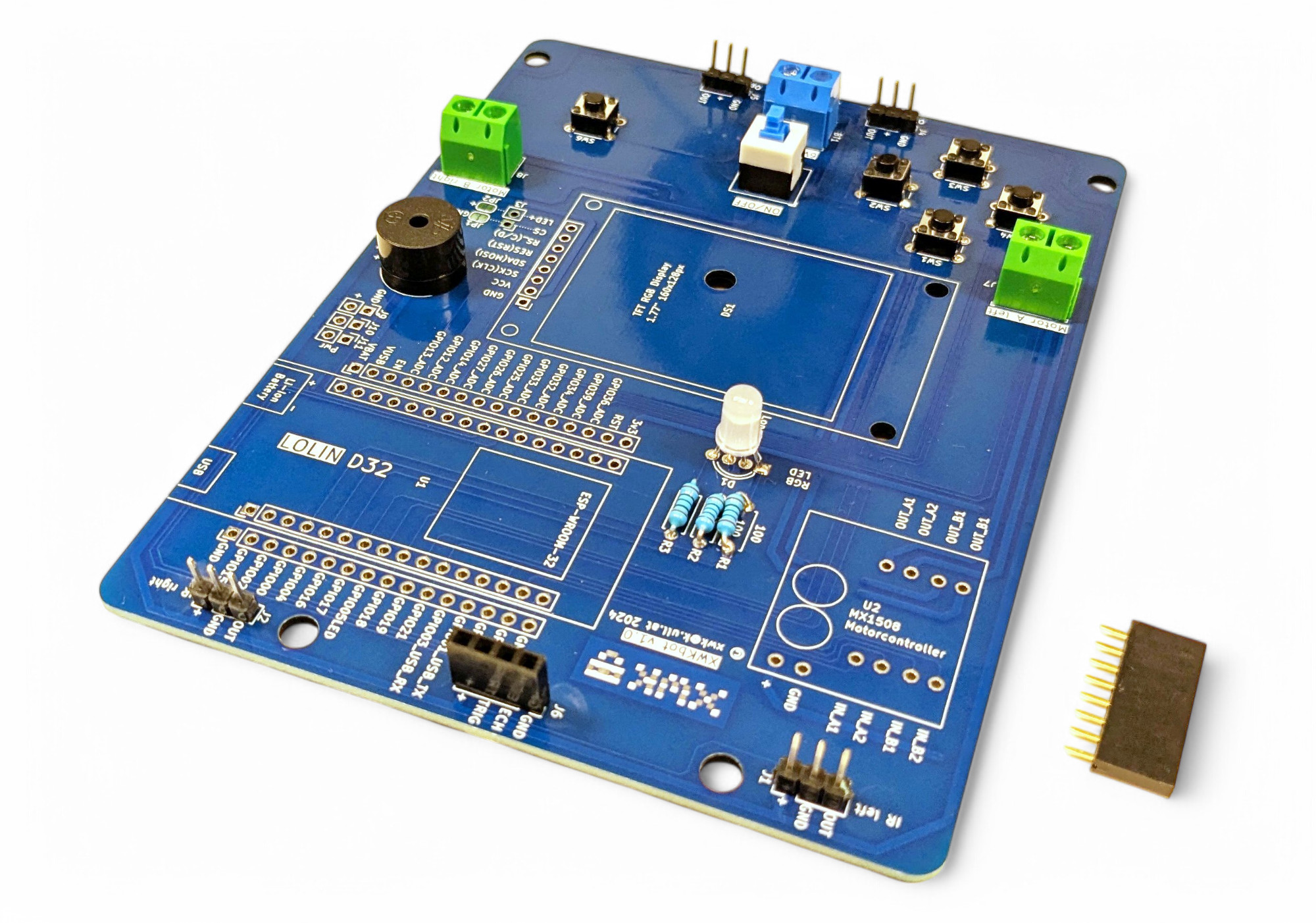
Here you can see all the components we'll be using. Look at the circuit board carefully. Can you see the connections between the individual holes for the components?
A circuit board or PCB (Printed Circuit Board) consists of a flat plate made of insulating material with conductive copper traces applied to it. These traces connect the various electronic components without having to connect everything with wires. Through these connections, complex electronic circuits can be realized in a very small space, which forms the basis for modern technology like smartphones, computers, and other digital devices.
Pro tip for circuit board assembly: start with the lowest components. This way you can turn the board over without components falling out. The lowest components on the XWK-Bot are the resistors.
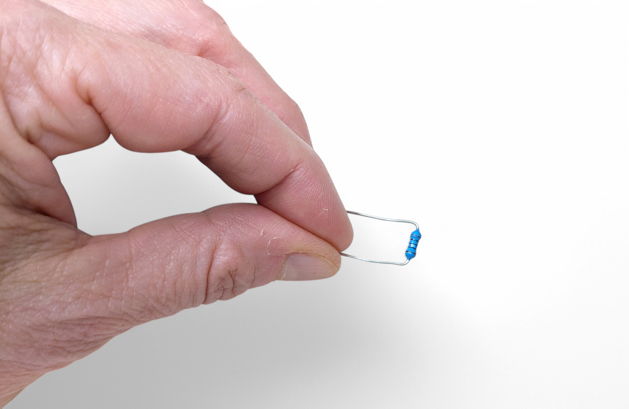
Resistors make it harder for current to flow. How strong a resistor is is indicated in "Ohms Ω", and you can read the value from the colored rings.
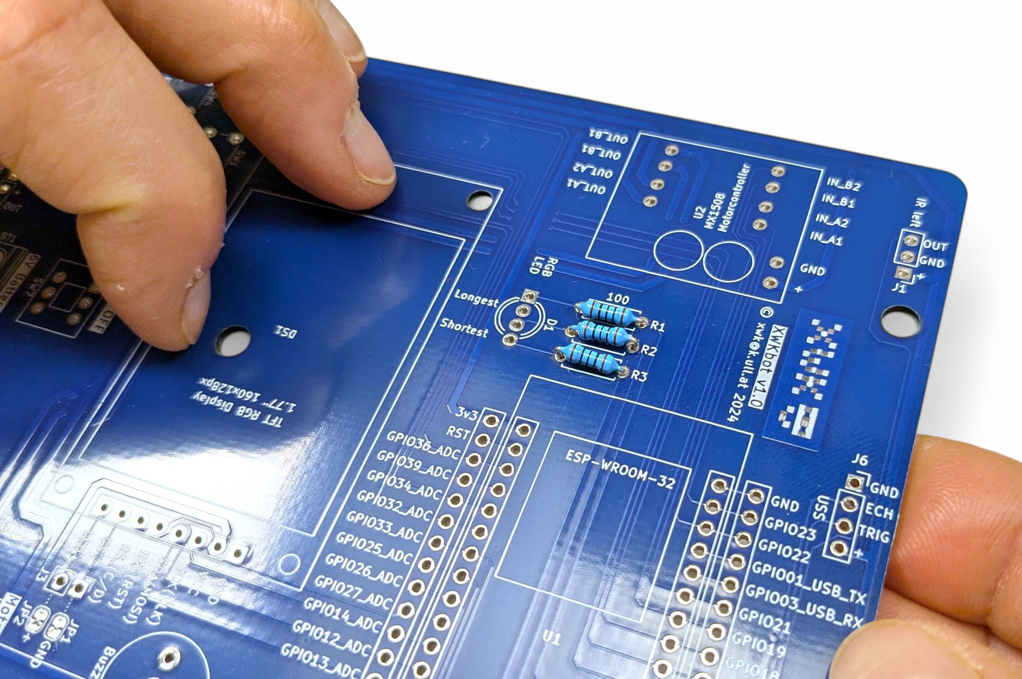
Find the spot for the resistors on the circuit board. They are labeled R1, R2, and R3 ("R" stands for "Resistor"). These three pre-resistors will protect our colored LED (Light Emitting Diode) from burning out.
Bend the resistor wires as close as possible to the "body" at a right angle:
Find R1, R2, and R3 on the circuit board. Push the resistors through the holes in the circuit board from above. Then turn the board over and bend the wires slightly apart, then the resistors won't fall out.
Now it's time to solder! If you've never soldered before, read the chapter at the beginning of these instructions!
As a right-hander, it's best to hold the soldering iron in your right hand and the solder in your left hand. Rest your hands on the table so your palms touch the table. This will help you shake less. Don't leave the soldering iron on the joint unnecessarily long, as the component can be damaged by the heat! One second is completely sufficient.
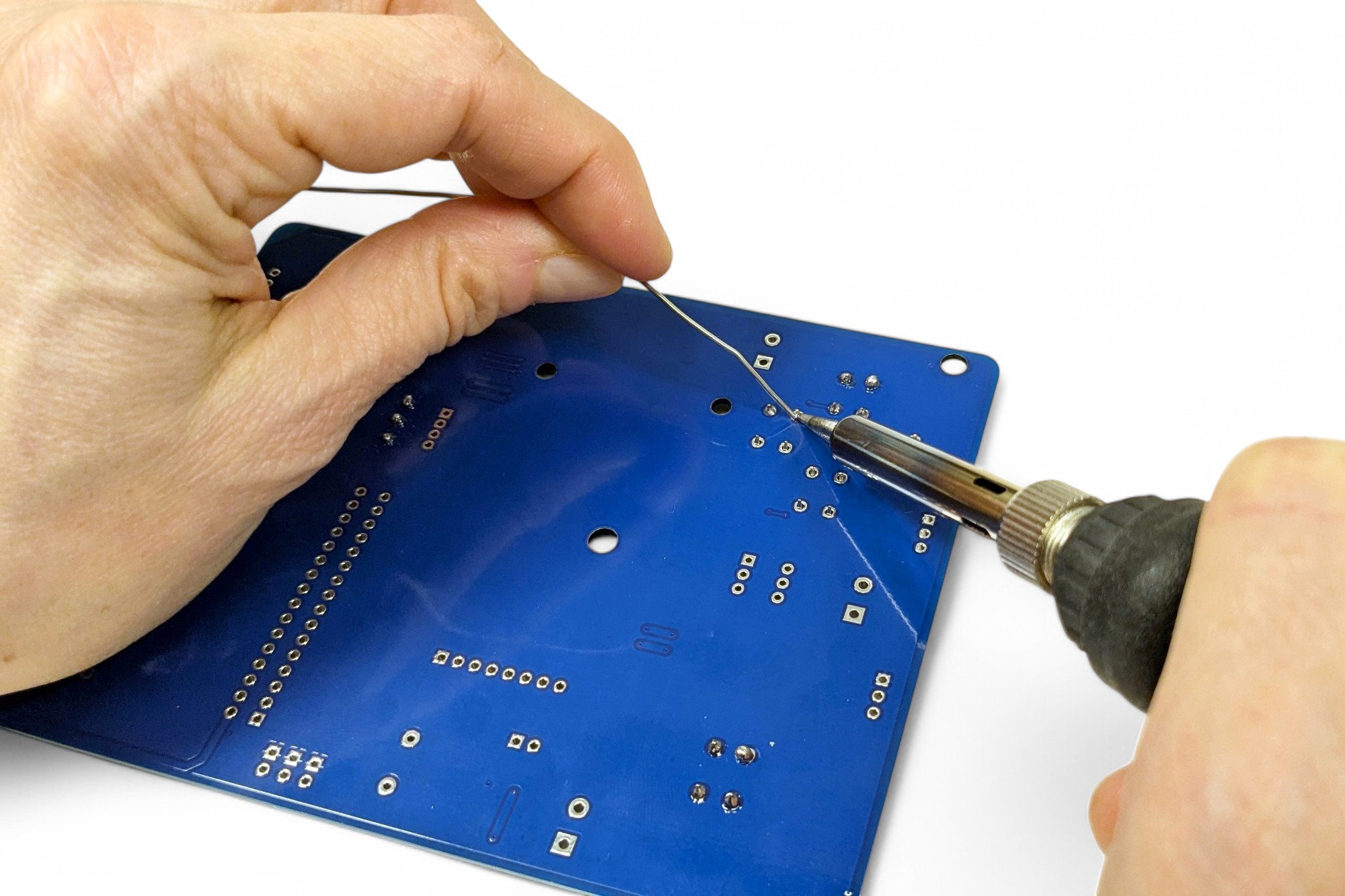
Position the tip of the soldering iron so that the tip touches both the silver ring of the circuit board and the resistor wire.
Now bring the solder to the soldering iron tip and melt enough solder at the tip to form a nice cone. If you can still see part of the hole in the circuit board, it was too little solder. If a ball forms, it was too much.
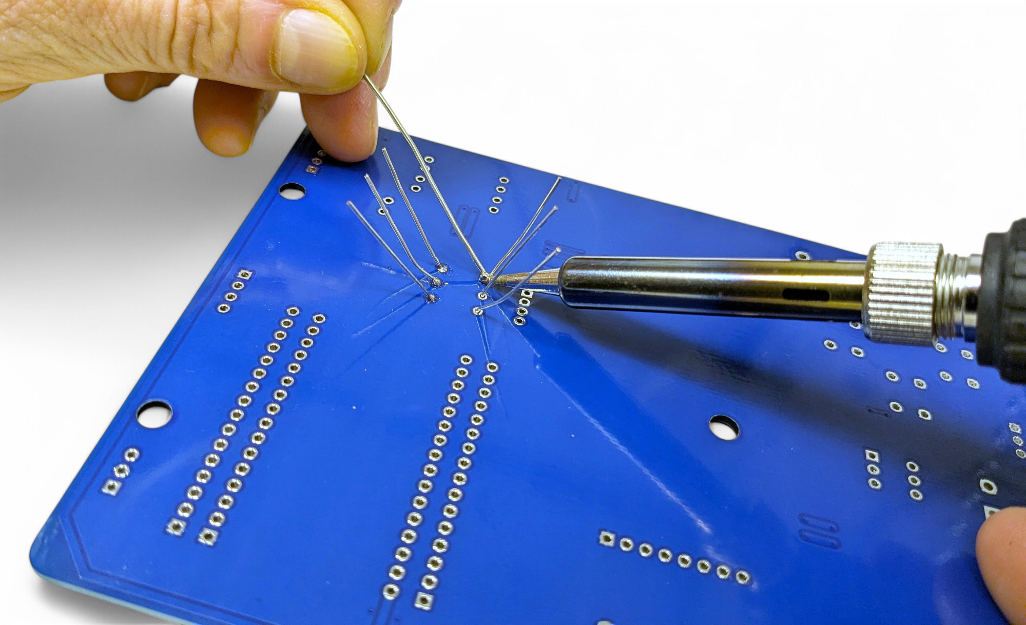
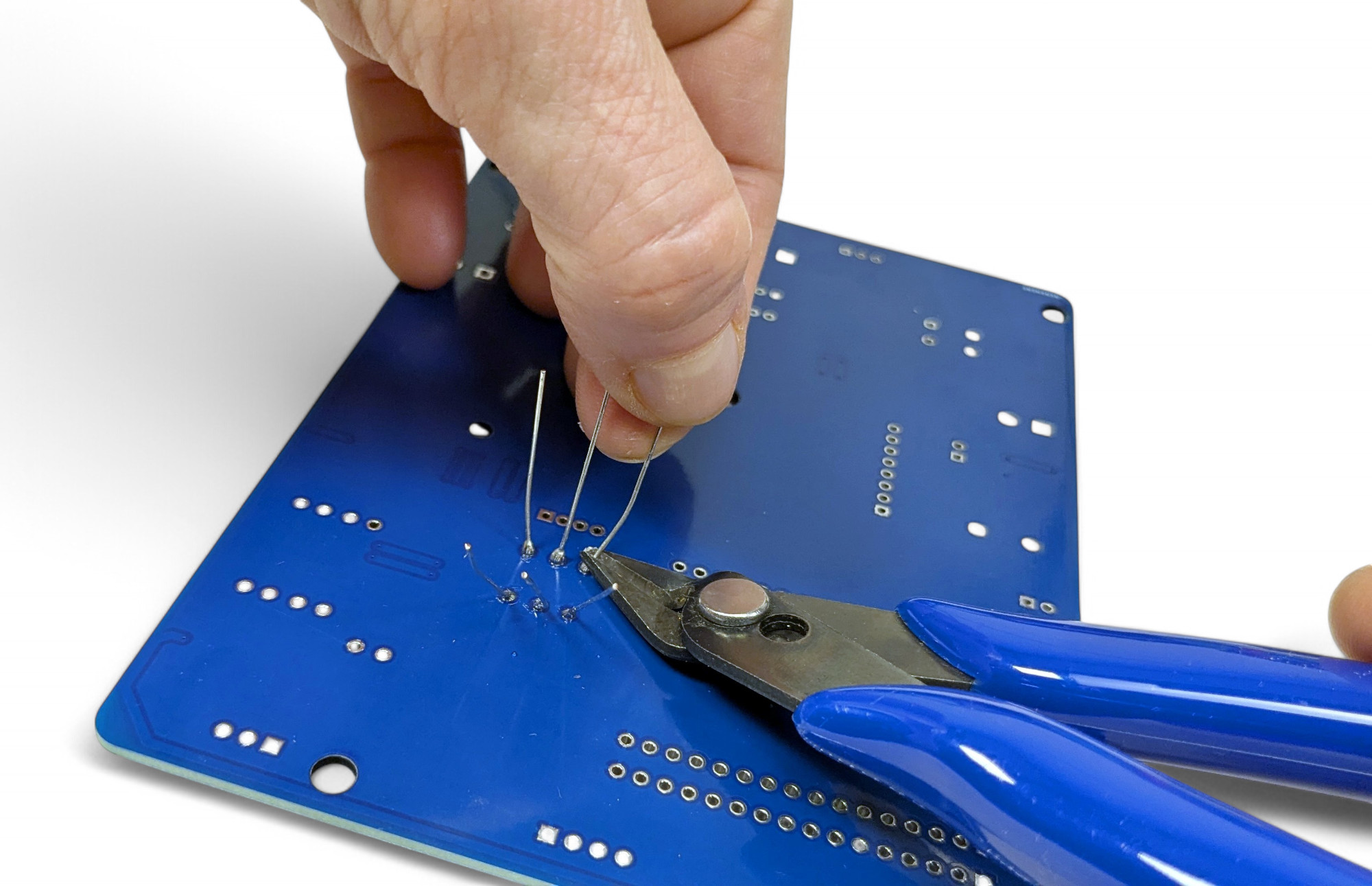
Now cut off the protruding wires directly above the solder joint with the side cutters:
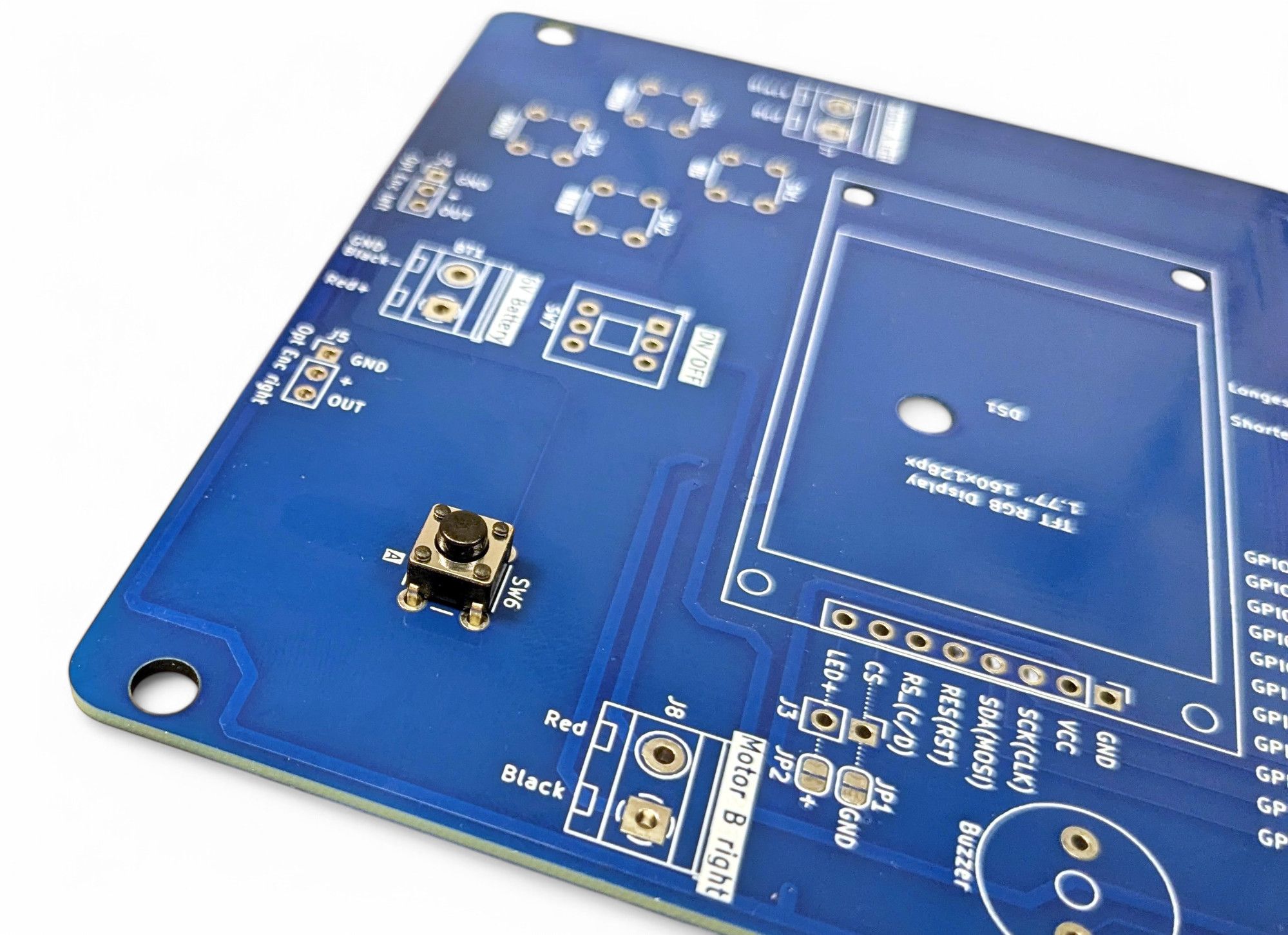
The next-lowest components are the buttons. Buttons are switches that normally don't make an electrical connection. But when you press them, two metal parts touch inside and electrical current can flow. When you release the button, the contact is broken again by a spring. The buttons are labeled "SW1" through "SW6" - "SW" stands for "Switch". Push all switches into the circuit board. You can't do anything wrong here, as the polarity (direction) doesn't matter. The switches should hold themselves in the circuit board through the bent "feet". Then carefully turn the board over and solder all button connections:
Bravo, you've now soldered a gamepad like from a game console!
Next, we'll solder in the RGB Light Emitting Diode (LED). Here, three light-emitting diodes with the colors red, green, and blue are built into one housing. From these three primary colors, you can mix all colors!
Diodes are electronic components that only let current flow in one direction. Light Emitting Diodes (LED) emit light. They come in various colors. Attention, since current can only flow in one direction, you must pay attention to the current direction (polarity)!
Bend the four connection wires of the LED slightly apart so they fit into the holes on the circuit board. Now find the right spot: "D1".
Pay close attention to how you solder in the LED! You must find the longest and shortest connection of the LED and solder them in according to the labeling on the circuit board!
TODO: additive color mixing

Now we'll solder in our small speaker so the XWK-Bot can make sounds!
This is a piezo buzzer, an electronic component that generates mechanical vibrations through the application of an electrical voltage to a piezoelectric material, which are perceived as an audible tone.
Find "BZ1" on the circuit board and solder in the speaker. The direction of the connections doesn't matter.
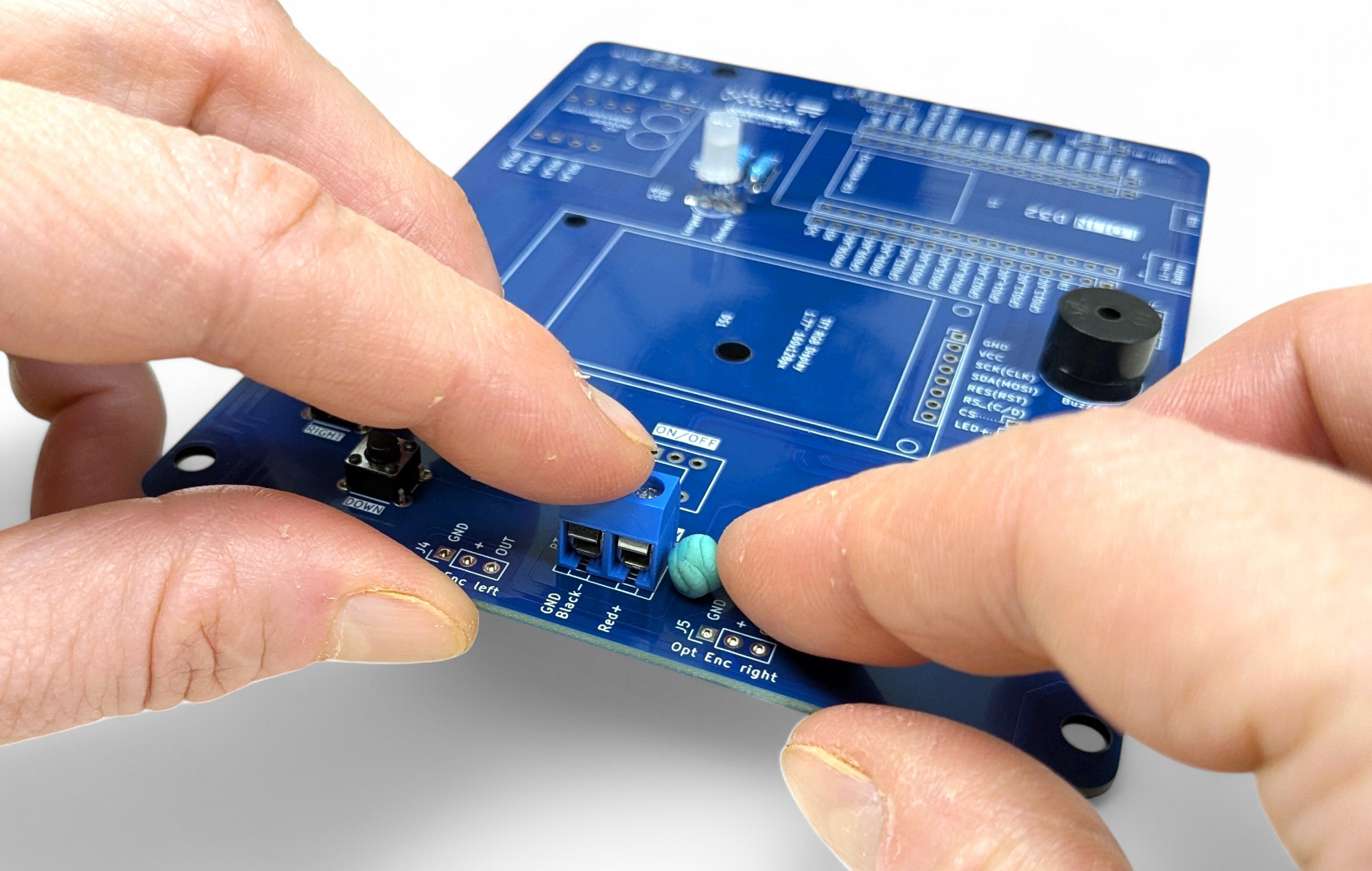
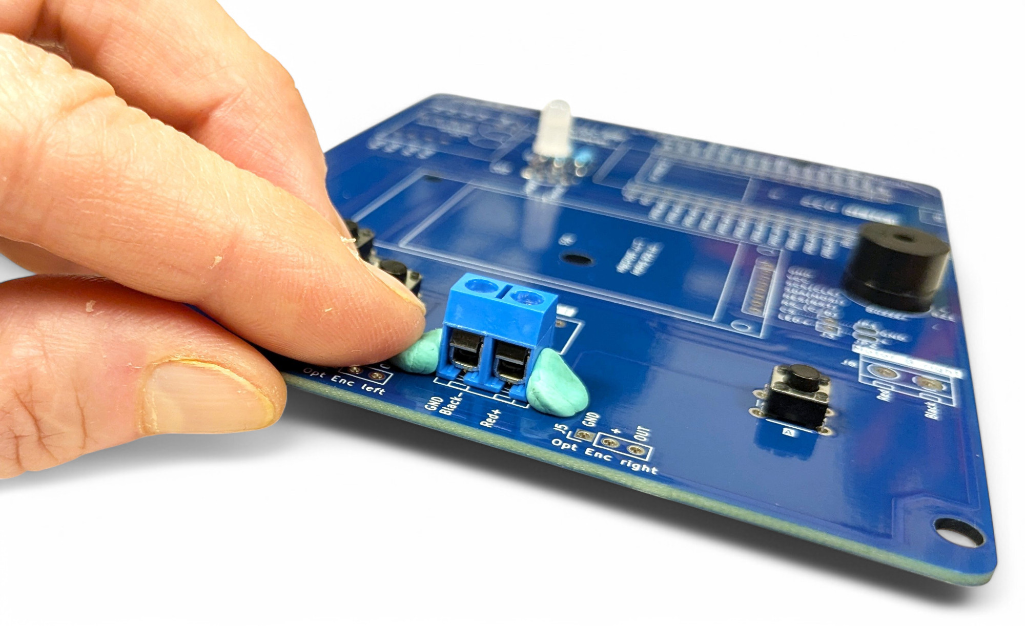
Terminal blocks, also called screw terminals, are used to mechanically and electrically connect wires or cables to a circuit board safely without needing solder connections.
We use a blue terminal block in the middle for the battery holder, and two green ones on the left and right for the motors.
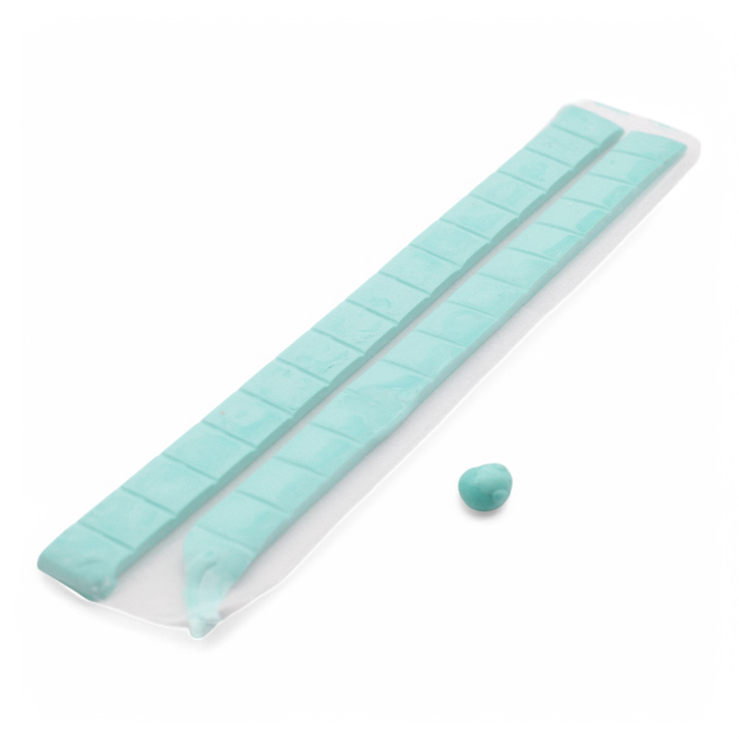
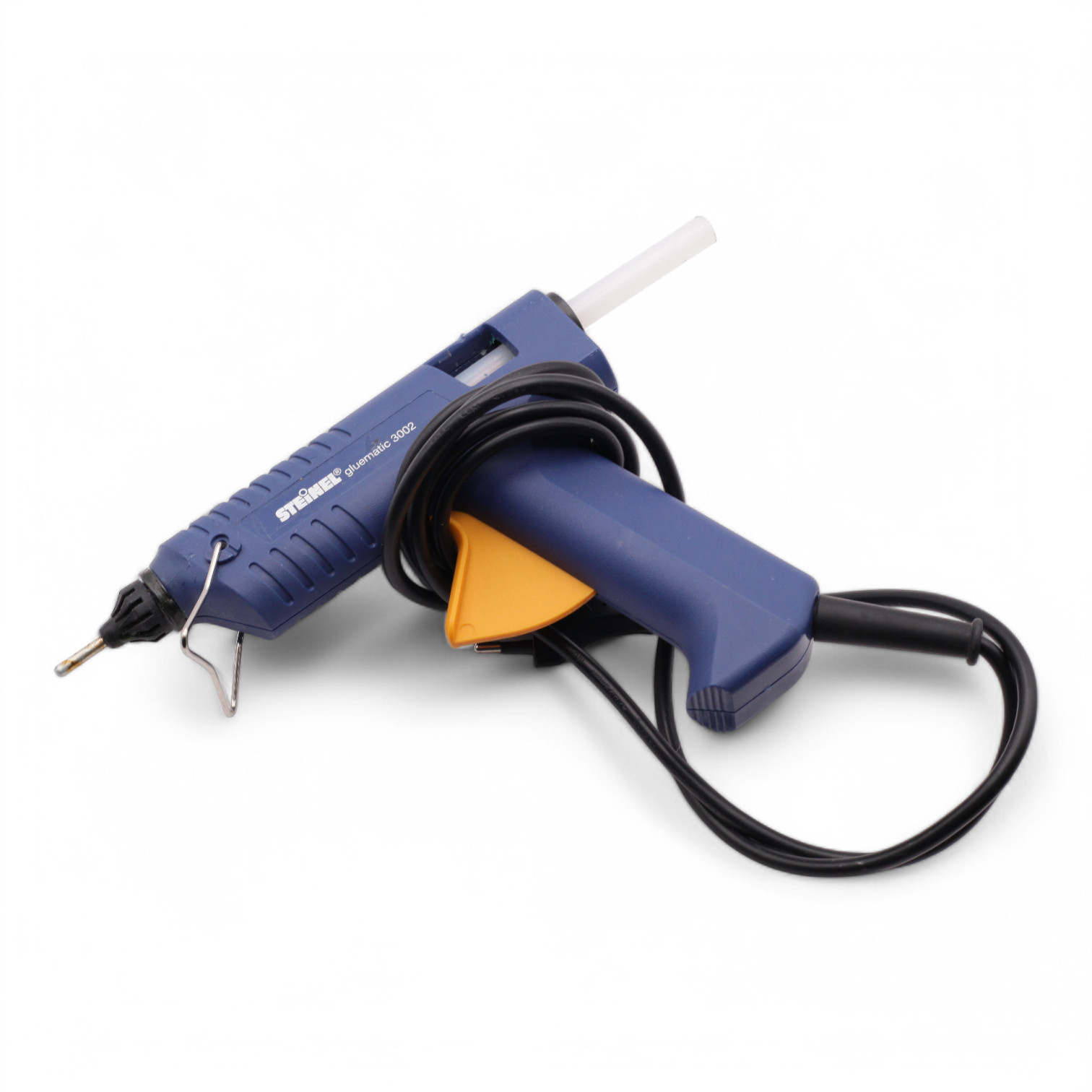
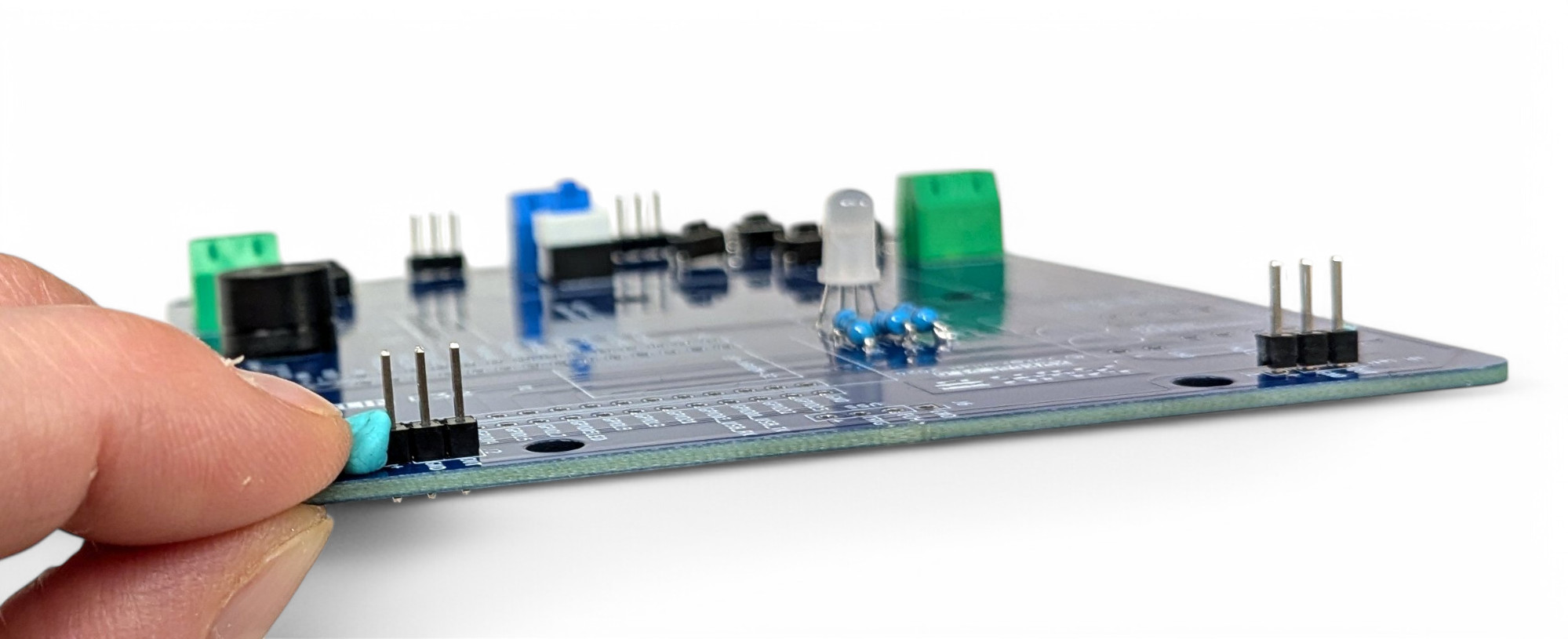
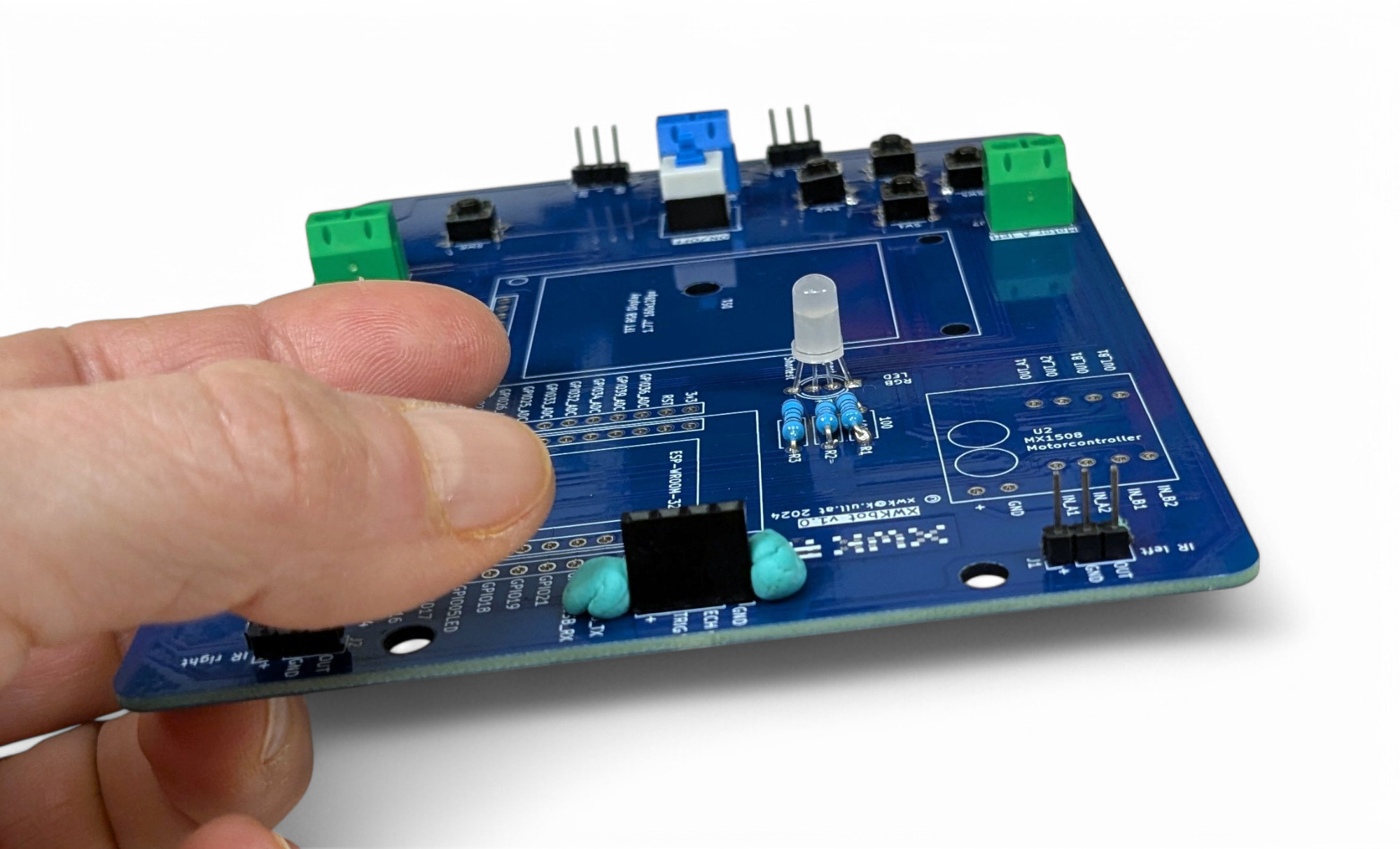
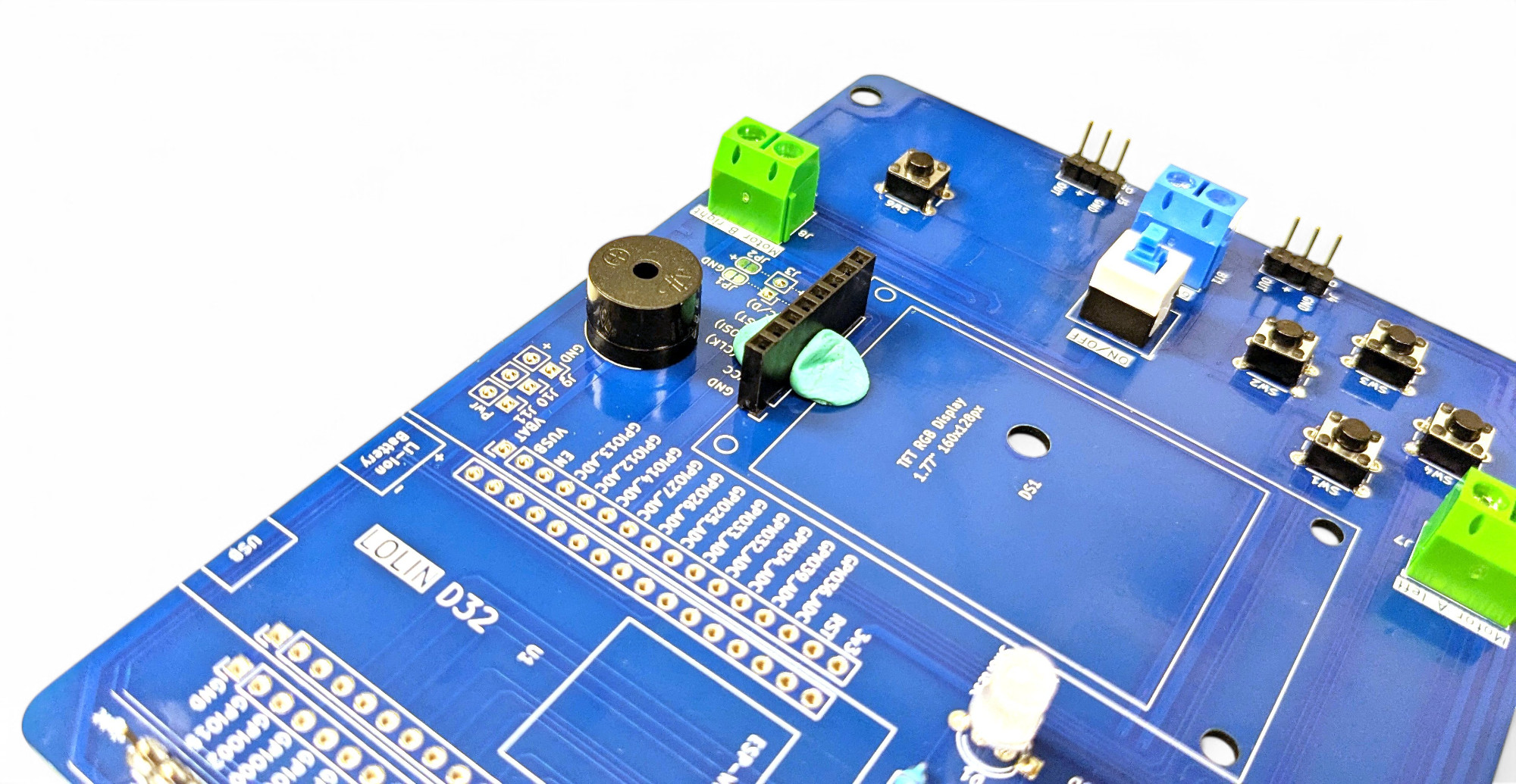
Use a drop of hot glue or small balls of sticky putty (Tac-It, manicure) so they don't fall off when turning over the circuit board:
TODO: solder in green ones
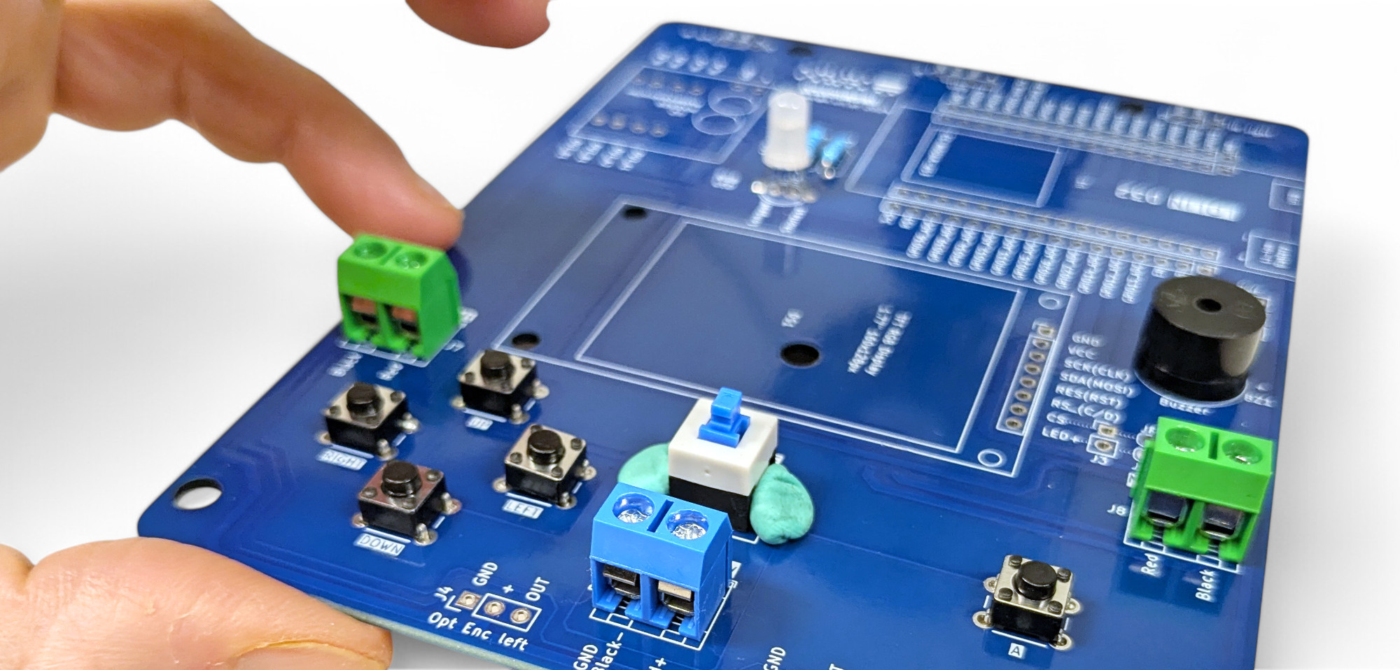
Now we'll solder in the on/off switch right next to the blue terminal block.
For the infrared light sensors, we need two male pin headers with three pins each. Take a side cutter and cut off the required length from the long strip.
TODO: photo 2x3
Then find the matching spots "J1" and "J2" labeled with "IR" (Infrared) at the top of the circuit board. Use putty or hot glue again to fix the component. Then turn the board over and solder as usual.
For the ultrasonic sensor, we need a female socket header with 4 contacts. Find "J6" at the top center of the circuit board and solder in the connection:
Our small display also needs a female socket header, but this time with 8 contacts. Find the right spot for the display connection in the center of the circuit board:
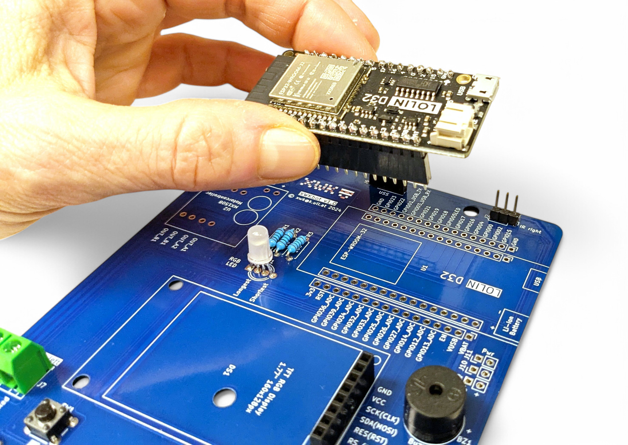
The remaining female, long socket headers we need for connecting the ESP microcontroller "LOLIN D32". It's best if you attach the socket headers directly to the microcontroller, and then to the circuit board:
Finally, we'll solder in the motor controller. It's needed to control the XWK-Bot's motors:
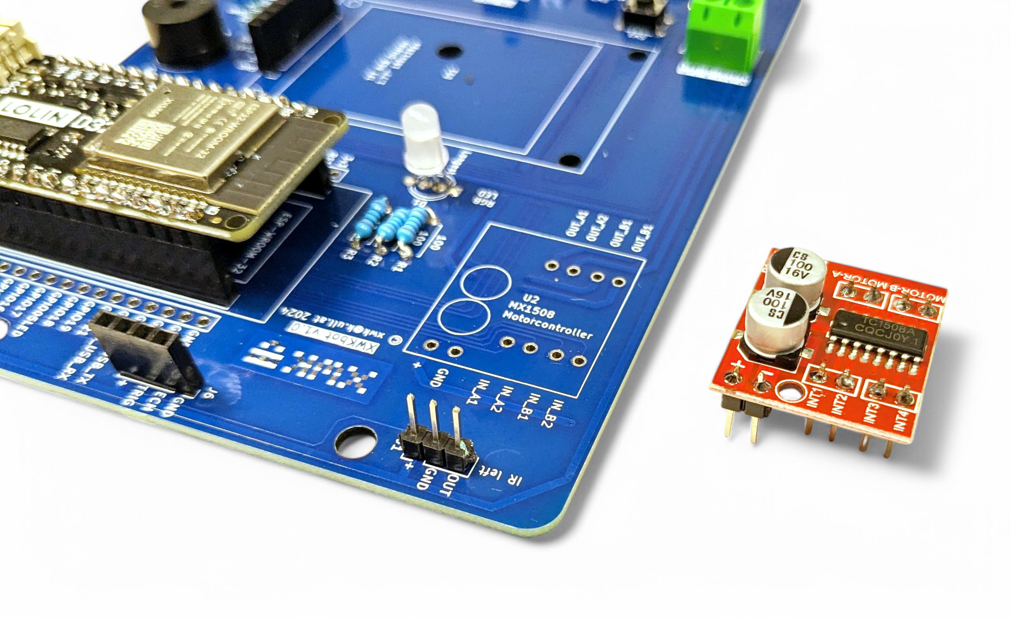
Bravo, well done!
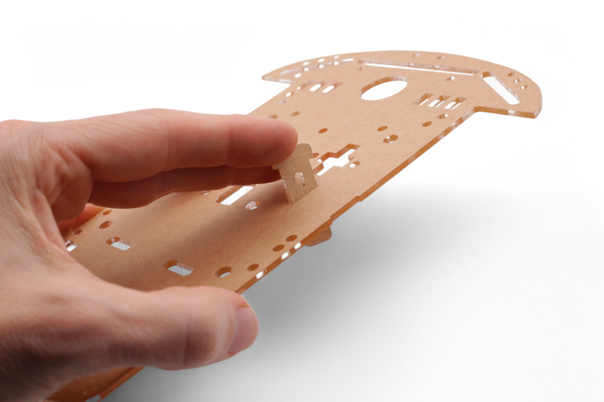
Now we'll finish assembling the robot. Turn the bot over and thread the motor wires to the top side:
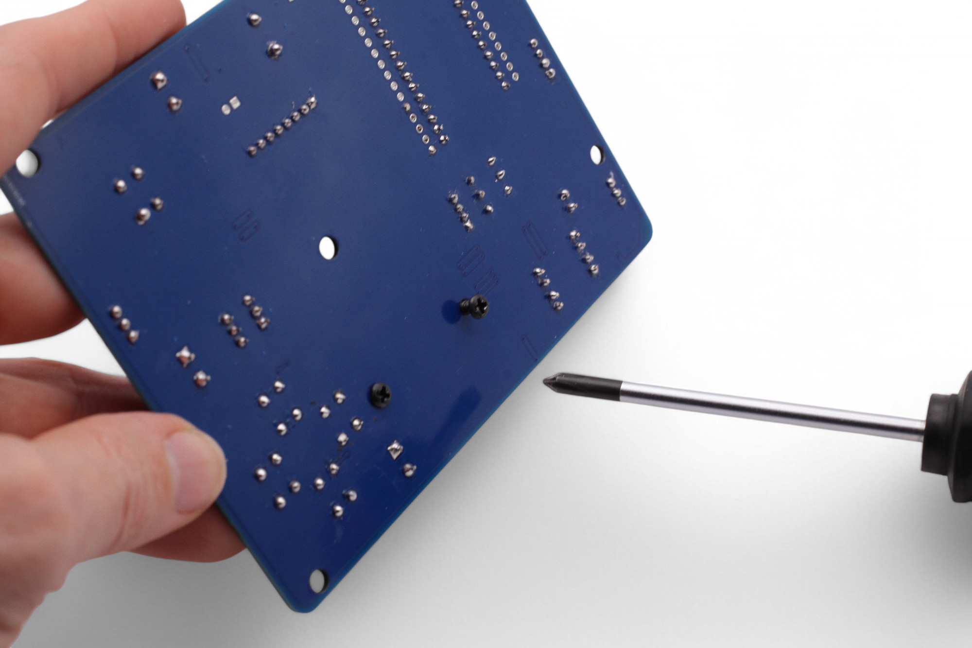
Now find the 3D-printed circuit board spacer and attach it with 5 screws.
First screw in the 5 screws only loosely, then tighten them:
Screw the two infrared sensors onto the 3D-printed holder:
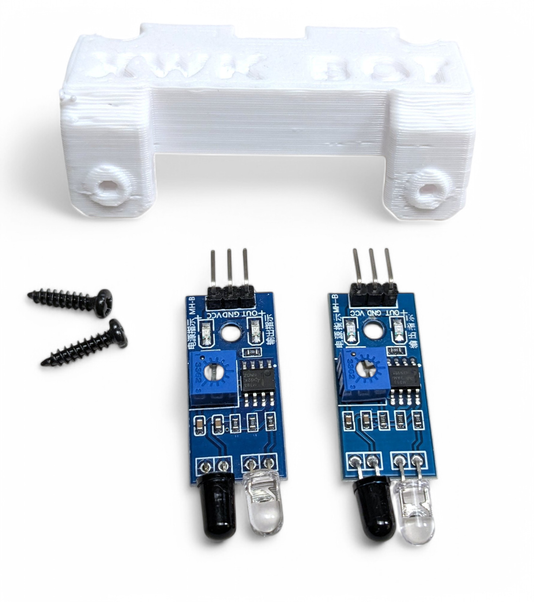
Now place the holder for the infrared sensors on the base plate. It fits together like a puzzle:
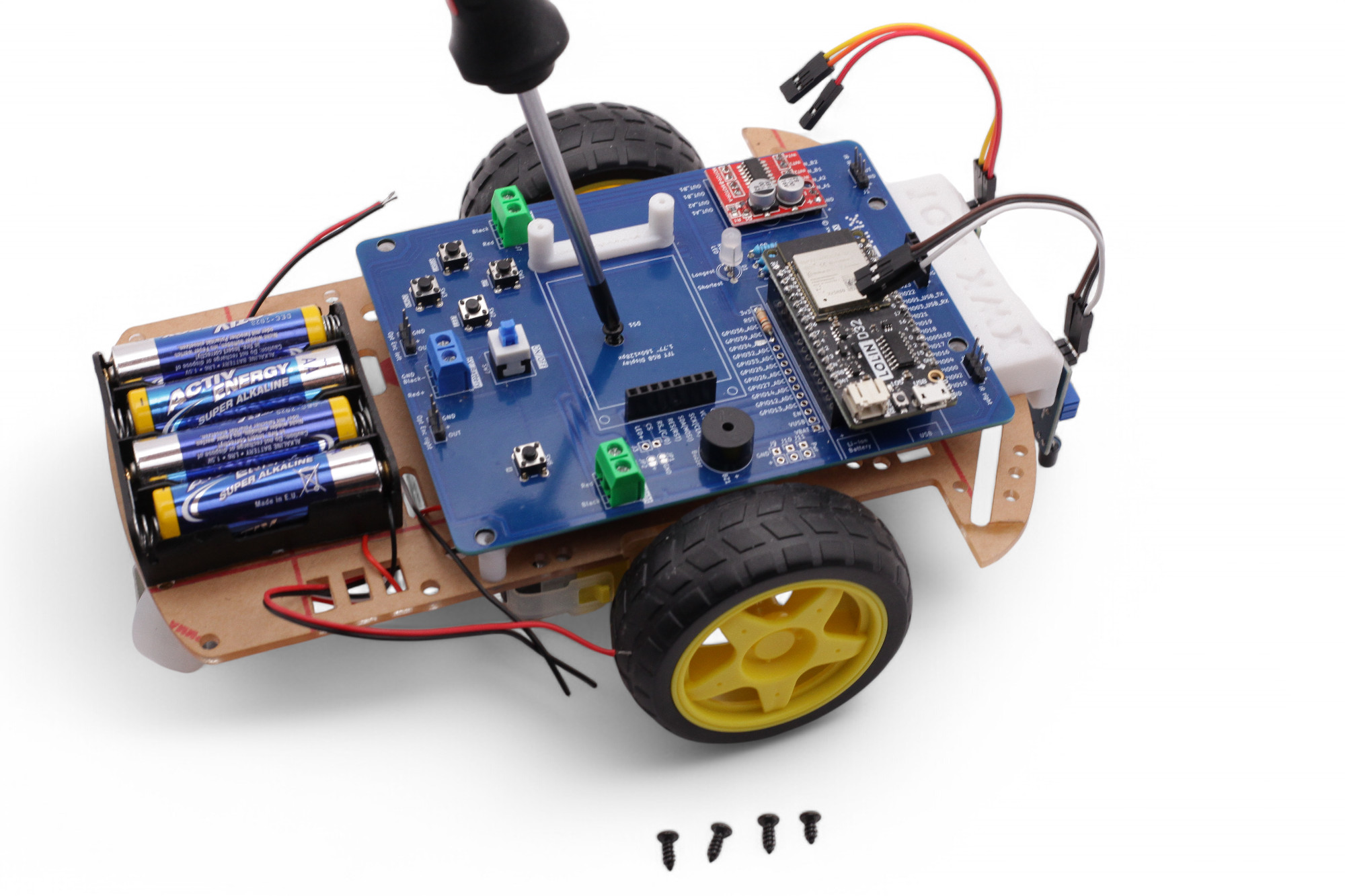
Screw the spacer for the display onto the circuit board:
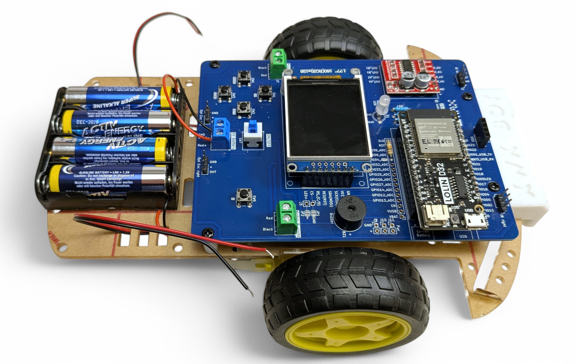
Now attach the circuit board to the base plate. First the screw in the middle, then at the four corners. Again, first screw in the 5 screws only loosely, then tighten them all:
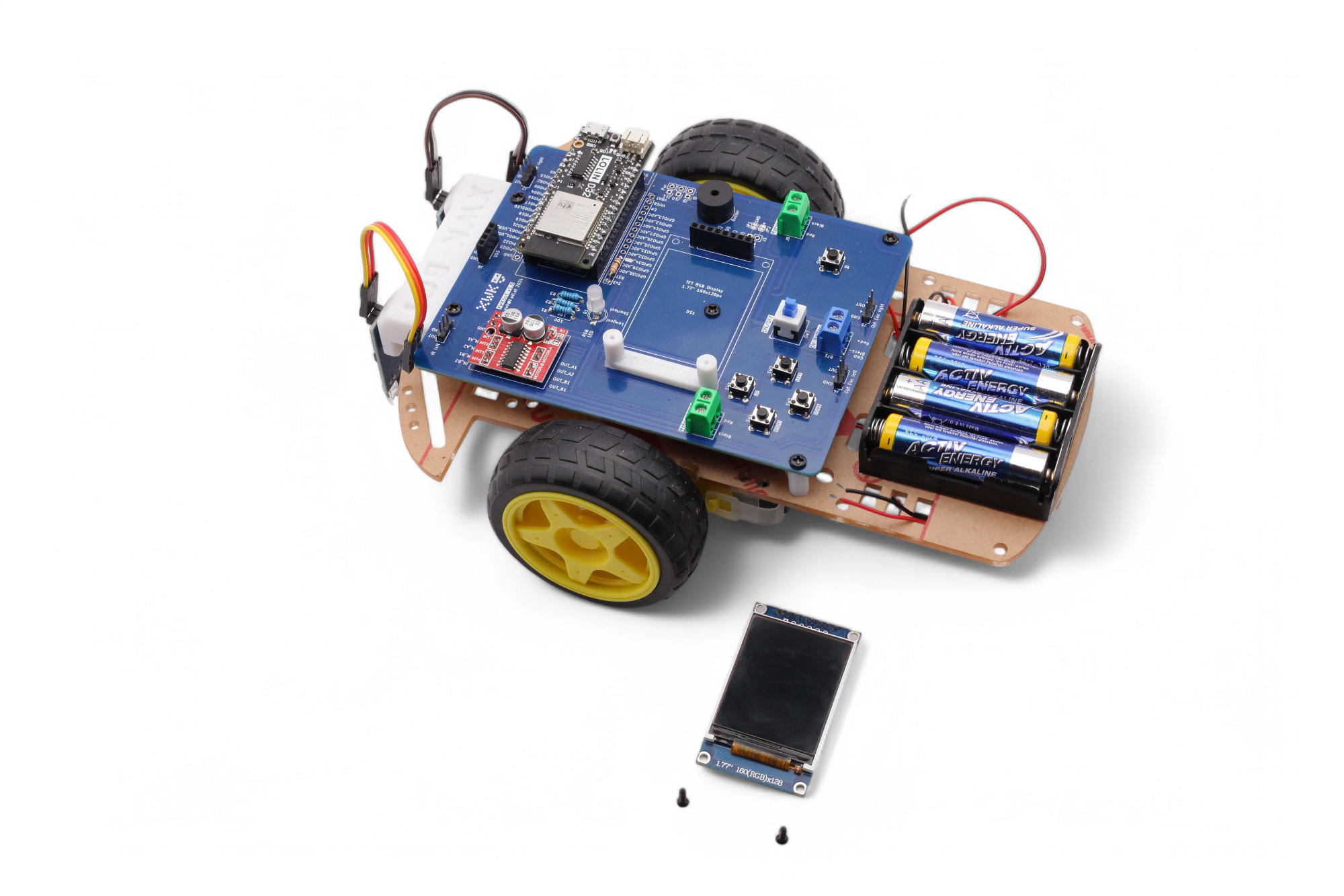
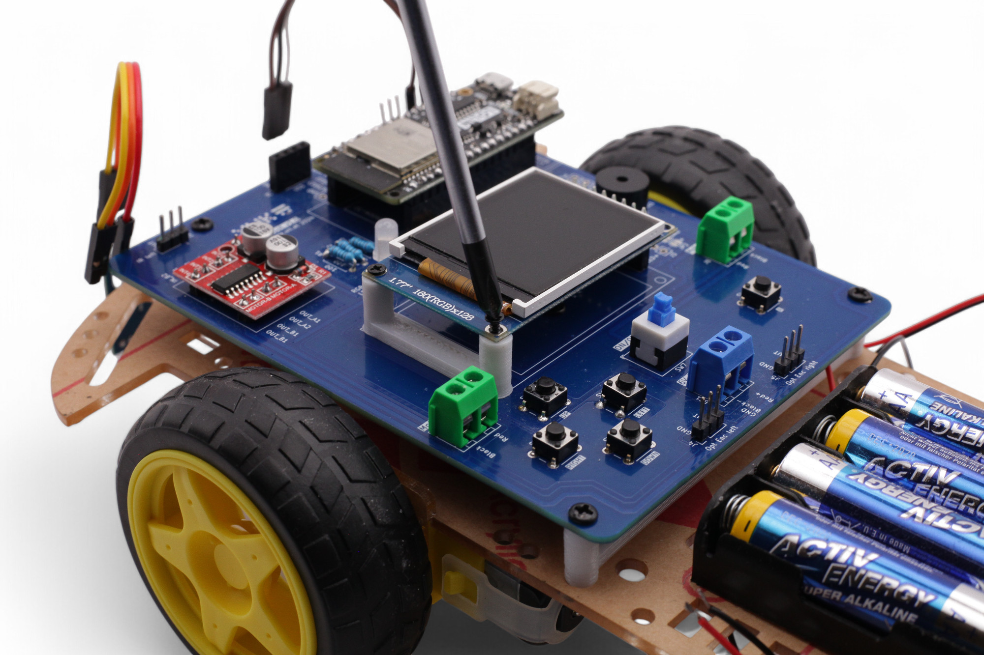
Push the display on and secure it with two small screws:
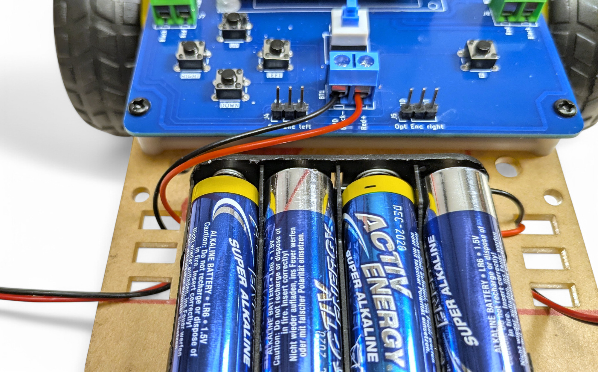
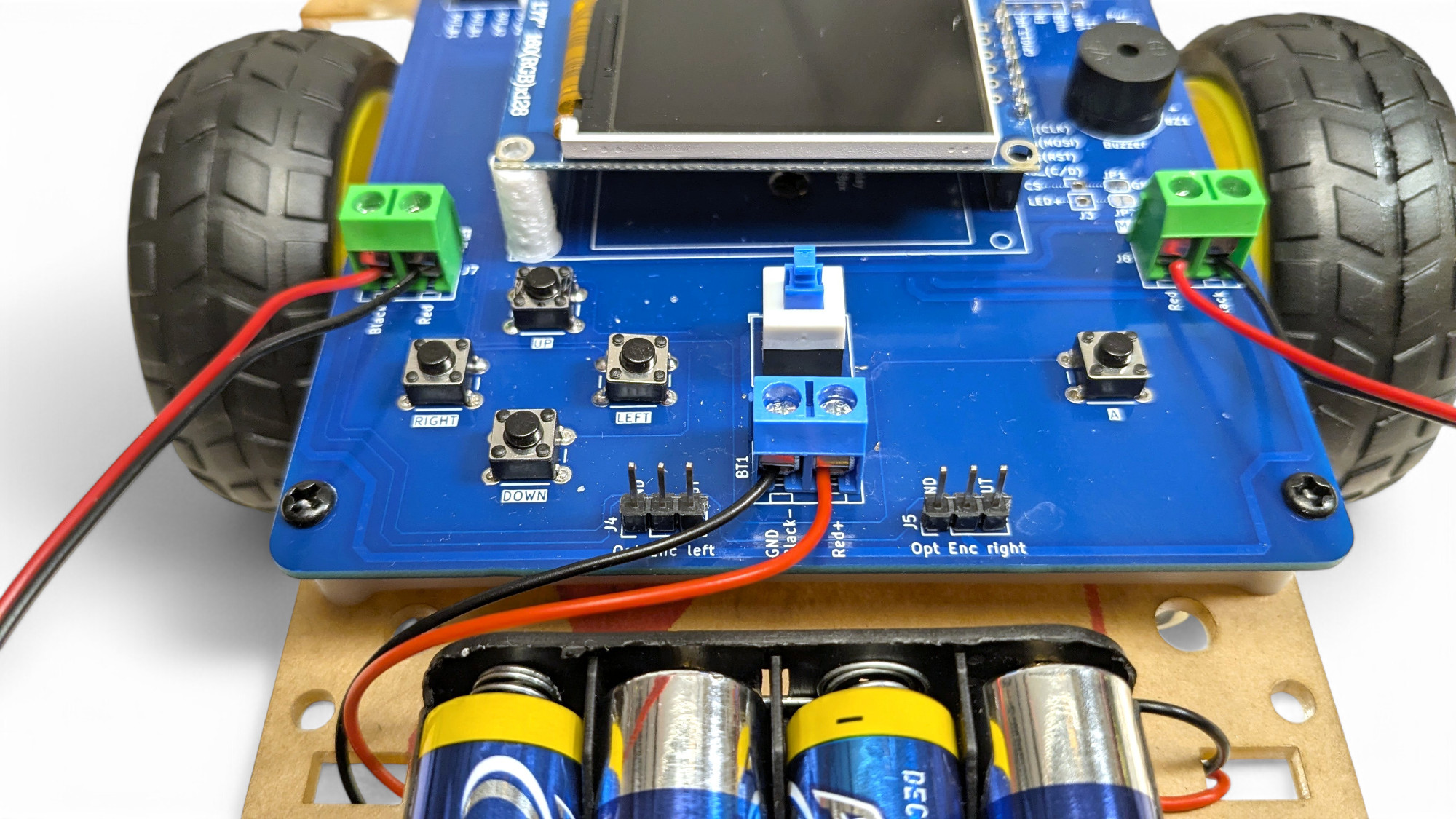
The battery holder cable is a bit too long. Try to route it well. For example: thread the cable to the underside and back up on the other side. Now we'll connect the battery connection cable to the blue terminal block.
Attention, absolutely pay attention to polarity! Red = "+ (positive pole) and Black = "- (negative pole)! If you swap these, you can destroy the robot!
Push the bare cable ends into the terminal block and tighten the screws.
Repeat the same process for the motor connection cables:
(Left side reversed: Red wire to BLACK, Black to RED)
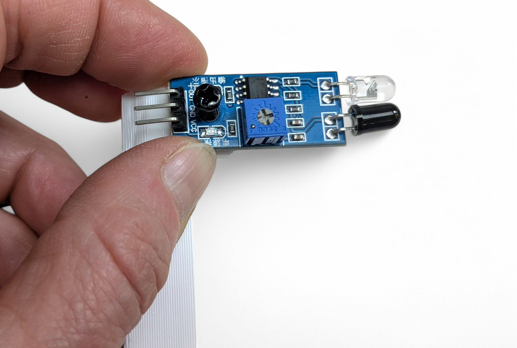
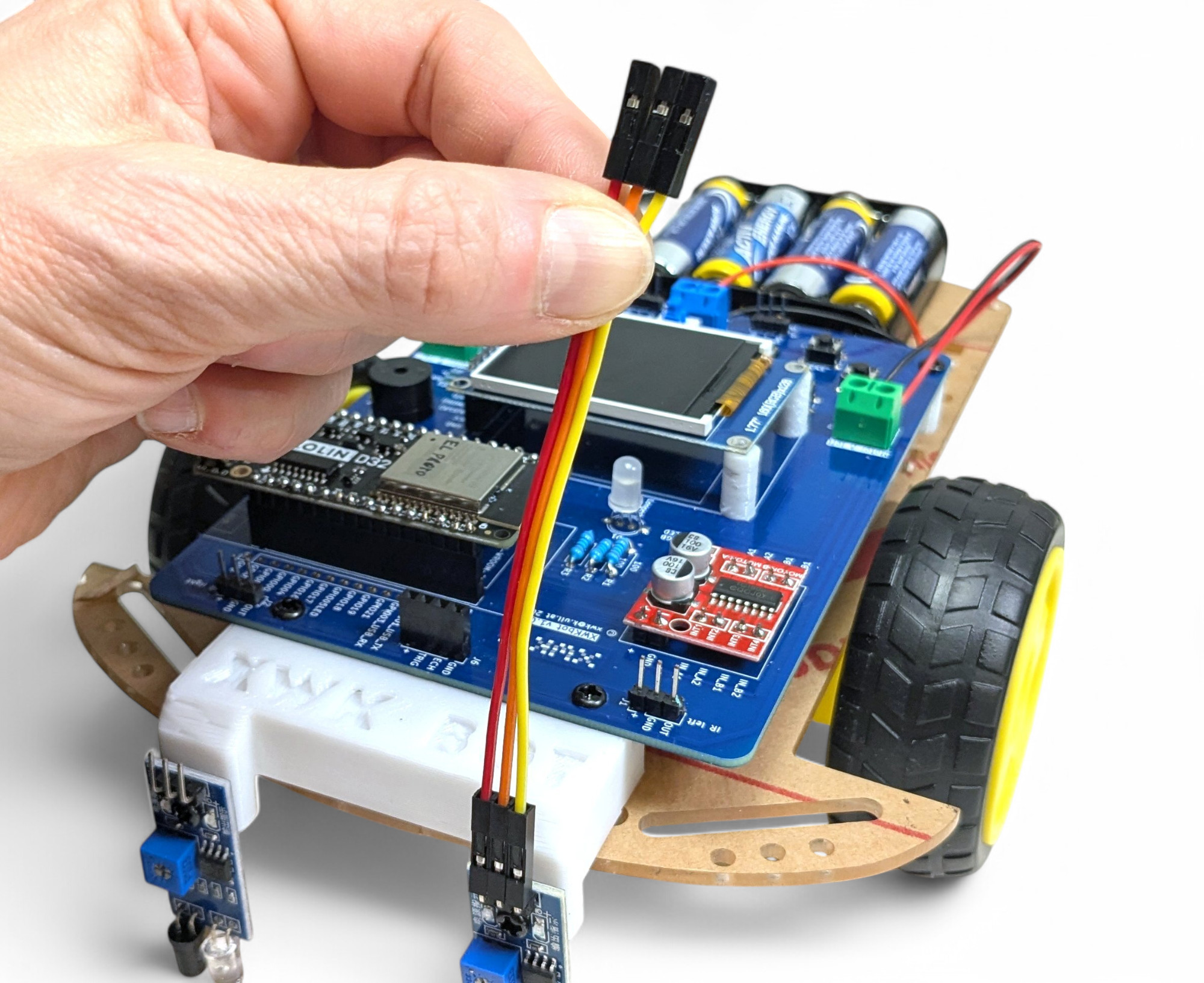
Now we'll connect the infrared sensors. We need two cables with three conductors each. To do this, separate three conductors each from the "rainbow" flat ribbon cable.
Then push one end onto the sensors, and the other end onto the circuit board.
Attention, absolutely pay attention to polarity! The connections must not be twisted/swapped, otherwise the sensor will be destroyed!
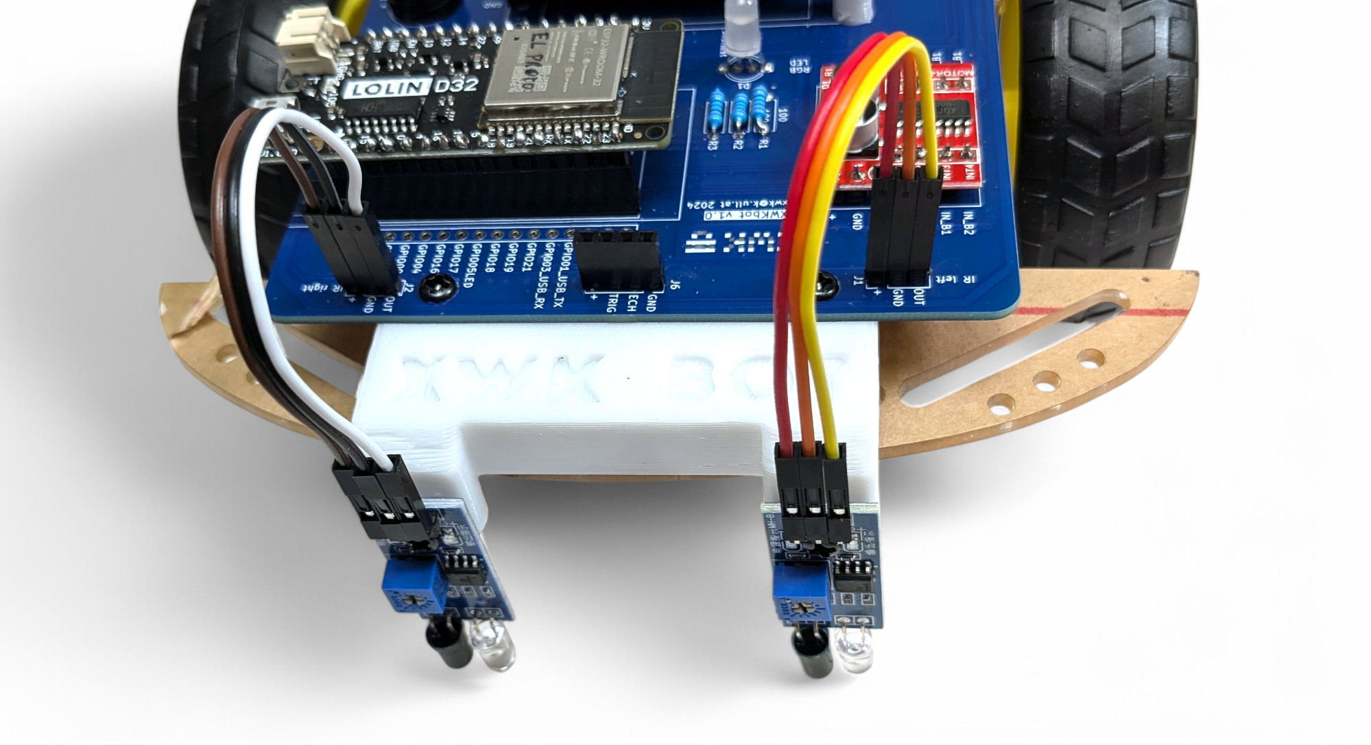
Now just plug in the ultrasonic sensor:
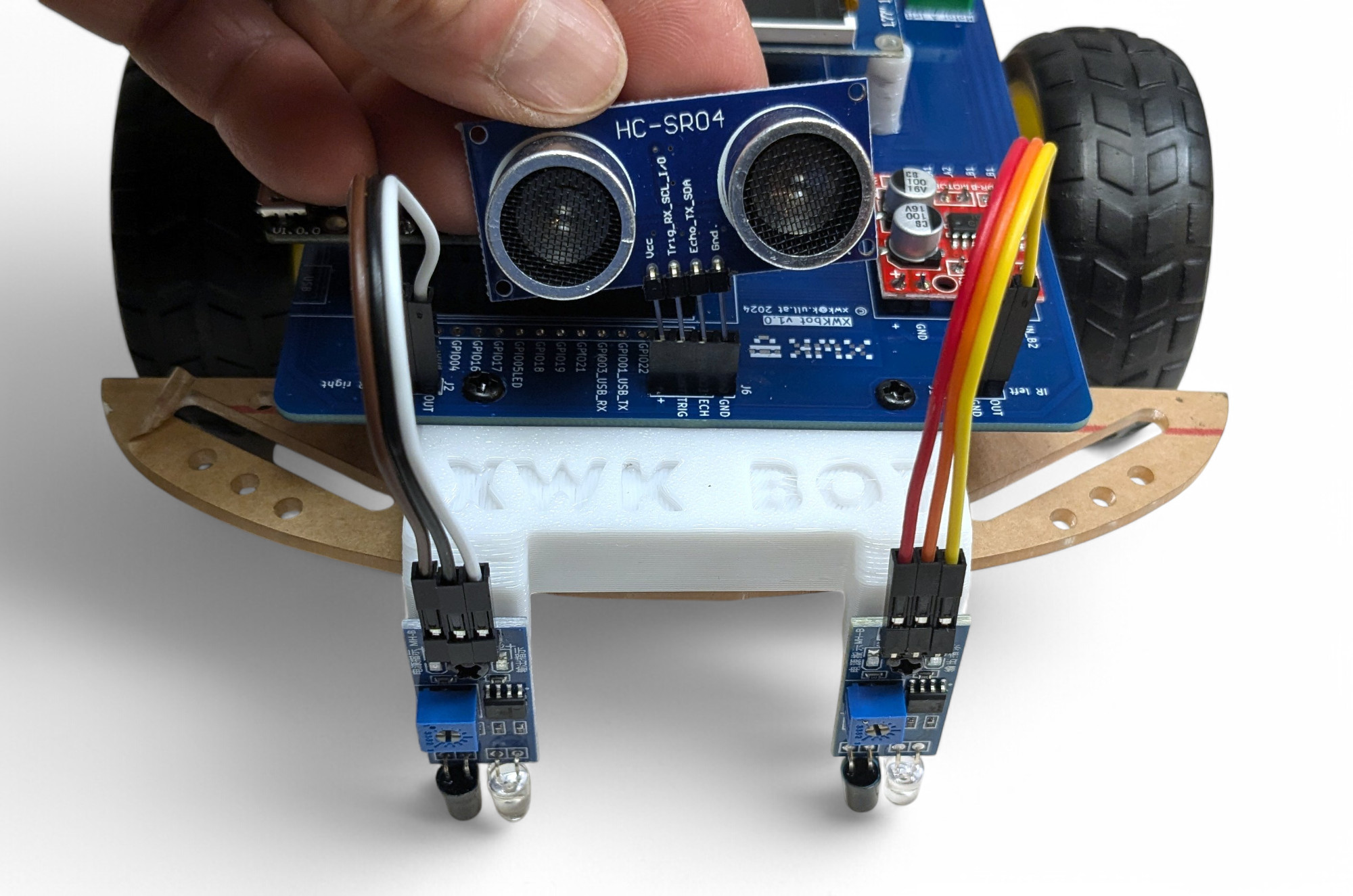
With the ultrasonic sensor, the bot can detect the distance to objects. An ultrasonic sensor works like a bat's hearing. It sends out sounds so high that humans can't hear them anymore. Then the sensor listens for how quickly the echo comes back to calculate the distance to objects. Bats use exactly this principle to "see" in the dark and avoid obstacles or find prey.
An infrared light sensor works like an eye that can only distinguish between light and dark. However, for infrared radiation and not for visible light. This "eye" is the dark LED on the sensor. The sensor also has a built-in "flashlight" that emits infrared light. That's the transparent LED on the sensor.
Both infrared sensors need to be calibrated to properly recognize the difference between light and dark. This is called calibration. Here's how:
Bravo, you've almost made it! Now let's test if all functions of the XWK-Bot work correctly.
The bot has a test program built in. Here's how to start it:
Here's a brief explanation of the tests. If something doesn't work, jump to the "Troubleshooting" chapter.
Move the bot over light and dark surfaces. The output on the display should always correctly show "bright" (=light) or "dark" (=dark).
Press "A" to go to the next test.
The display shows you the distance to the nearest detected object. Move the bot in different directions and check if the distances are approximately correct. The sensor can "see" up to 3m.
Press "A" to go to the next test.
The left motor should turn forward a bit, then backward. Then the right motor should turn forward a bit, then backward.
If a motor turns in the wrong direction, you need to swap the cables in the corresponding terminal block. Then restart the test and check if the direction is now correct.
You should hear a tone
You should see all colors: red, green, blue, yellow, magenta (pink), cyan (turquoise) and white.
Press all buttons in any order.
Did everything work? Hearty congratulations! You have successfully built the XWK-BOT!
Don't get too frustrated, it's completely normal for mistakes to happen. A super power for life is learning to find errors systematically and to learn or understand why they occur.
Here are some general tips:
Nothing lights up, nothing moves. Test:
Best to test with a multimeter if you have access to one. Set the multimeter to voltage and touch the measuring probes (black to black, red to red) to the screws of the blue terminal block. You should see a value between 4.5 and 6 volts.
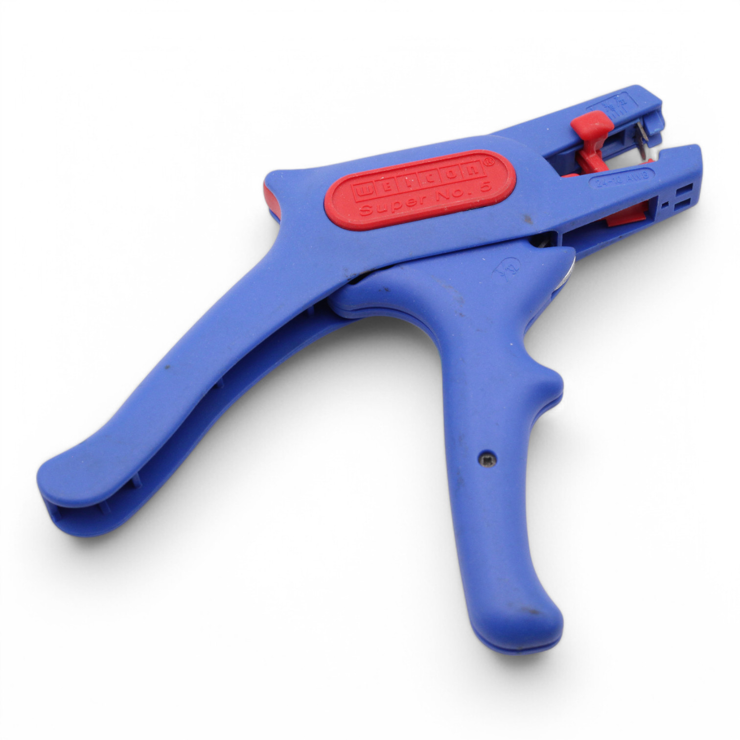
Sometimes the cables are poorly attached to the battery holder in the factory. This is unfortunately difficult to repair. You can claim this. Or you can try to strip the cables and clamp the bare wires between the battery and holder.